Wood board stamping and punching equipment for building materials

A kind of punching equipment and wood board technology, which is applied in wood processing equipment, fixed drilling machines, bark area/debris/dust/waste removal, etc., can solve the problems that the accuracy of wood strip punching cannot be guaranteed and the safety of workers, etc. To achieve the effect of optimizing the punching effect, standardizing the punching position, and preventing obstruction

Pending Publication Date: 2020-12-18
邹自强
View PDF5 Cites 5 Cited by
  • Summary
  • Abstract
  • Description
  • Claims
  • Application Information

AI Technical Summary

Problems solved by technology

[0005] In order to overcome the shortcomings of not being able to guarantee the accuracy of the punching of wooden strips and the safety of workers, the technical problem to be solved is to provide a punching and punching equipment for wooden boards for building materials that can improve the accuracy of punching wooden strips and reduce the danger of workers

Method used


Image

  • Wood board stamping and punching equipment for building materials
  • Wood board stamping and punching equipment for building materials
  • Wood board stamping and punching equipment for building materials

Examples


Embodiment 1

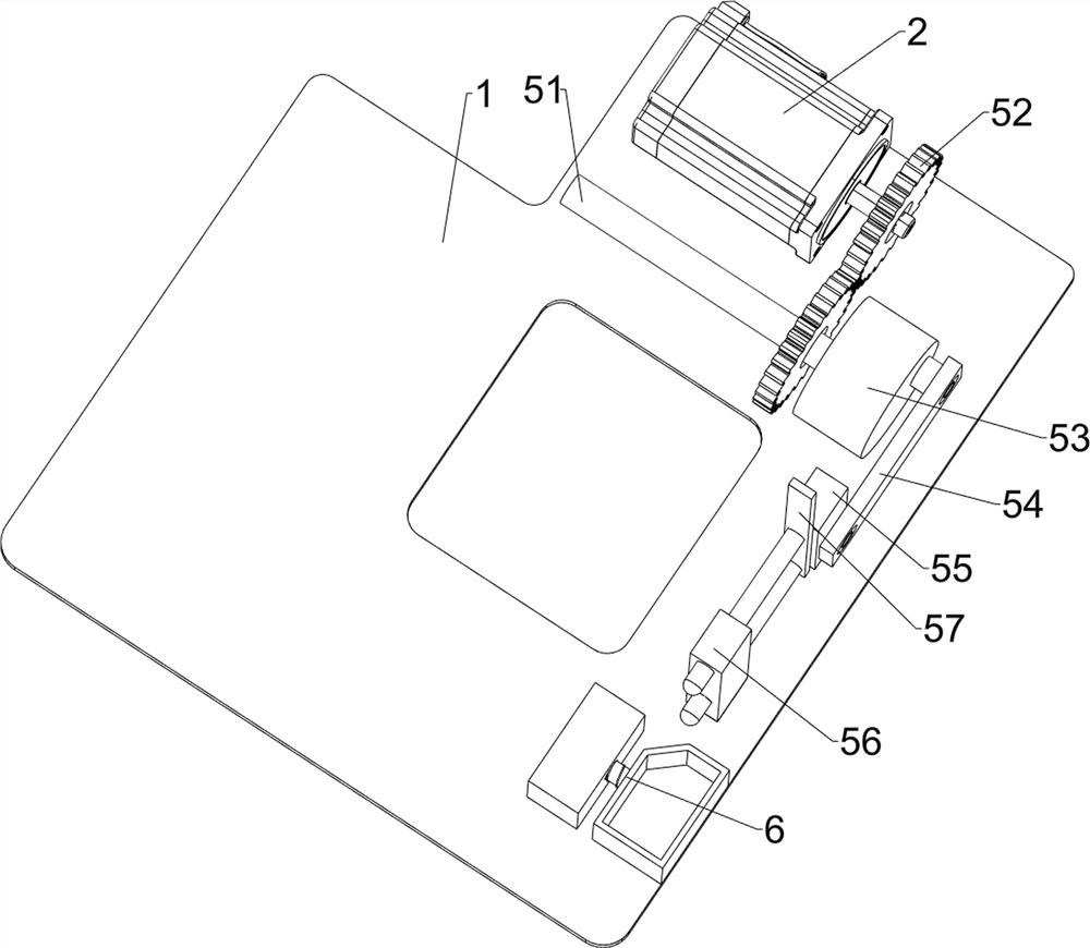
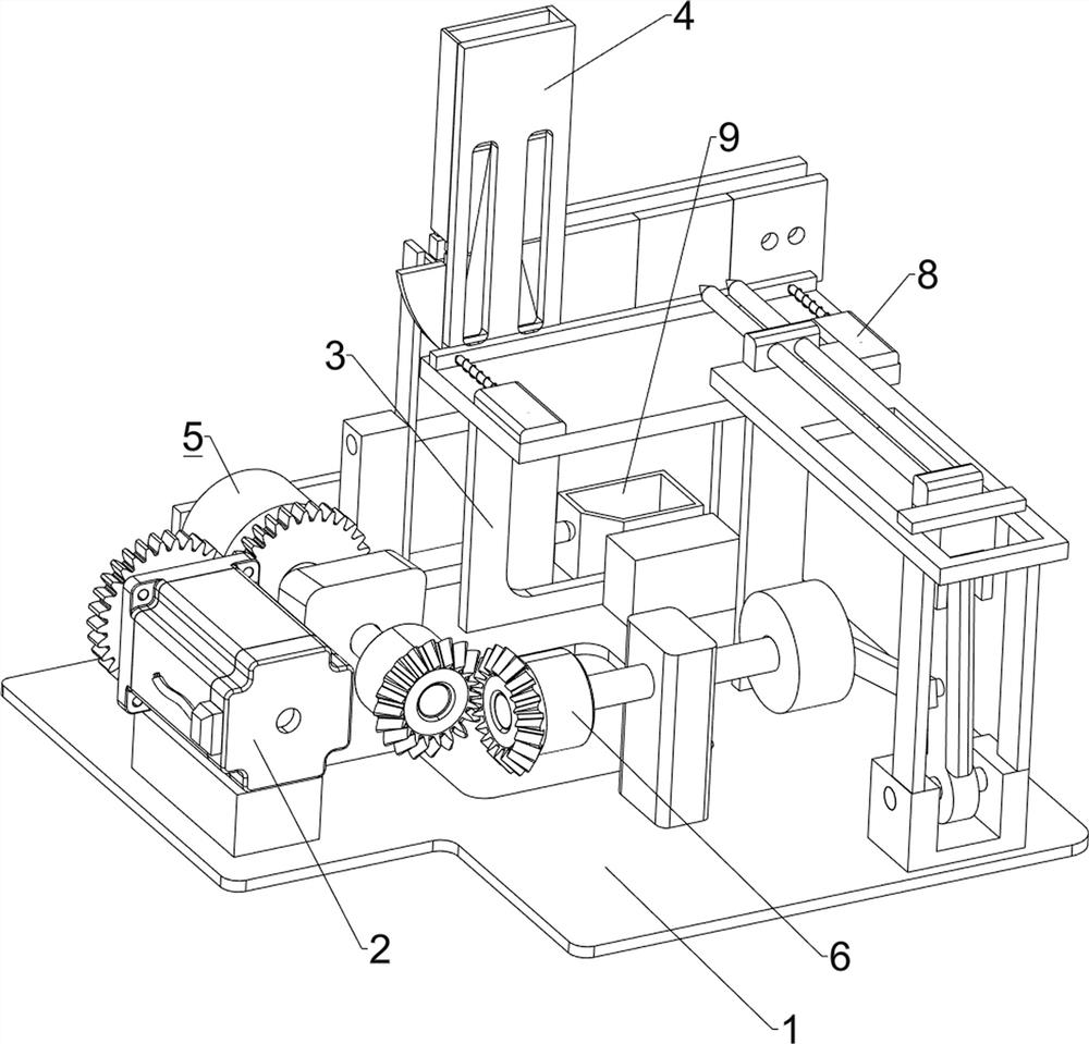
[0022] A kind of equipment for stamping and punching wood boards for building materials, such as figure 1 with figure 2 As shown, it includes a bottom plate 1, a servo motor 2, a mounting plate 3, a blanking box 4, a pushing mechanism 5 and a punching mechanism 6, a servo motor 2 is installed on the right side of the bottom plate 1, and a mounting plate is installed on the left side of the bottom plate 1. Plate 3, the upper right side of the mounting plate 3 is provided with a blanking box 4, the upper front side of the bottom plate 1 is provided with a pushing mechanism 5, and the upper rear side of the mounting plate 3 is provided with a punching mechanism 6.

[0023] When people want to punch holes in the planks, they usually need to manually punch holes in the planks, which cannot automatically punch holes in the planks. Therefore, people can use this device to first place the planks that need to be punched in the blanking box 4, Turn on the servo motor 2, the rotation o...

Embodiment 2

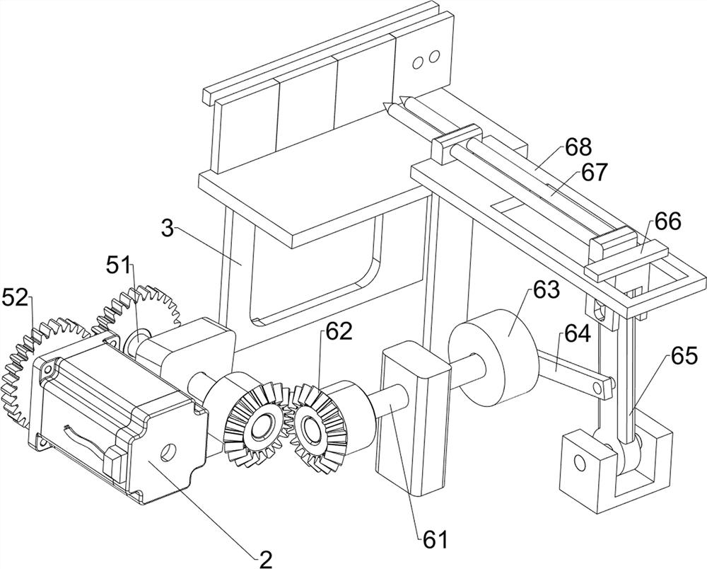
[0025] On the basis of Example 1, such as image 3 , Figure 4 with Figure 5 As shown, the pushing mechanism 5 includes a first rotating shaft 51, a spur gear 52, a first disk 53, a first rotating rod 54, a first push plate 55, a fixed block 56, a second push plate 57 and a sector baffle 58 , the bottom plate 1 is provided with a first rotating shaft 51 in a rotating manner on the right side, and a spur gear 52 is arranged on the front side of the first rotating shaft 51 and the output shaft of the servo motor 2, and the two spur gears 52 mesh, and the front end of the first rotating shaft 51 is provided with The first disc 53, the front side of the first disc 53 is rotatably provided with the first rotating rod 54, the left side of the bottom plate 1 is provided with a fixed block 56, and the sliding type in the fixed block 56 is provided with the first push plate 55, the first The push plate 55 is rotatably connected to the first rotating rod 54 , the second push plate 57...

Embodiment 3

[0030] On the basis of Example 2, such as figure 1 with figure 2 As shown, it also includes an adjusting bolt 7 and an elastic member 8. The front side of the mounting plate 3 is symmetrically provided with an adjusting bolt 7, and the rear side of the mounting plate 3 is provided with an elastic member 8 in a left-right and symmetrical sliding type. Elastic chute 9.

[0031] When punching holes, the wooden board may be unstable. At this time, the adjustment bolt 7 and the elastic member 8 can be adjusted to make the wooden board difficult to loosen and more stable when punching holes, so as to optimize the punching effect. When the pushing mechanism 5 When the left pushes the wooden block, the leftward movement of the first push plate 55 will drive the elastic chute 9 to move forward. During the hole, the sawdust that has punched will fall among the elastic chute 9, save the work that the workman cleans up after punching, and prevent the sawdust from hindering the work of ...


PUM


Abstract

The invention relates to punching equipment, in particular to wood board stamping and punching equipment for building materials. According to the wood board stamping and punching equipment for the building materials, the wood strip punching precision can be improved, and the risk of workers is reduced. The wood board stamping and punching equipment for the building materials comprises a bottom plate, a servo motor, a mounting plate, a discharging box, a pushing and blocking mechanism and a punching mechanism; the servo motor is installed at one side of the bottom plate; the mounting plate is arranged on the bottom plate; the discharging box is arranged at the side, close to the servo motor, of the mounting plate; the pushing and blocking mechanism is arranged at the side, close to the mounting plate, of the bottom plate; and the punching mechanism is arranged on the mounting plate. According to the wood board stamping and punching equipment, by means of the design of the pushing and blocking mechanism, wood boards are pushed leftwards, the wood boards are automatically moved so as to be matched with operation of the punching mechanism, the wood boards do not need to be moved manually, and the punching position of each wood board is more standard.

Description

technical field [0001] The invention relates to a punching device, in particular to a punching punching device for a wooden board used for building materials. Background technique [0002] Punching equipment is a kind of equipment for machine punching wood strips instead of manual punching. [0003] For the punching of wooden strips, the traditional method is to manually hold the wooden strips and push the wooden strips to punch holes. Due to manual punching, not only the position of each punching hole cannot be accurate, but also manual operation is difficult. It is easy to be accidentally injured by the machine. When punching wooden strips in the traditional way, the wooden strips are easy to slide, which will lead to inaccurate punching. With the trend of using automation equipment in the manufacturing industry to replace human hands, batch drilling is the future development direction , but the traditional method cannot keep up with the speed of batch opening. [0004] ...

Claims


Application Information

Patent Timeline
Patent Type & Authority Applications(China)
IPC IPC(8): B27C3/02B27G3/00
CPCB27C3/02B27G3/00
Inventor 邹自强
Owner 邹自强
Why Eureka
Try Eureka