Tool for machining

A technology for cutting processing and tools, which is applied in the direction of cutting tools, tool holders, and manufacturing tools for lathes. It can solve problems such as tool failure and cutting blades cannot be reliably maintained, and achieve the effect of optimizing elasticity.

Pending Publication Date: 2020-12-25
ZCC CUTTING TOOLS EURO
View PDF3 Cites 0 Cited by
  • Summary
  • Abstract
  • Description
  • Claims
  • Application Information

AI Technical Summary

Problems solved by technology

Such a construction has the disadvantage due to the delicate configuration of the bridge section that the cutting insert cannot be held securely
[0006] Other embodiments known from the prior art, in which narrow slots run

Method used


Image

  • Tool for machining
  • Tool for machining
  • Tool for machining

Examples


Embodiment Construction

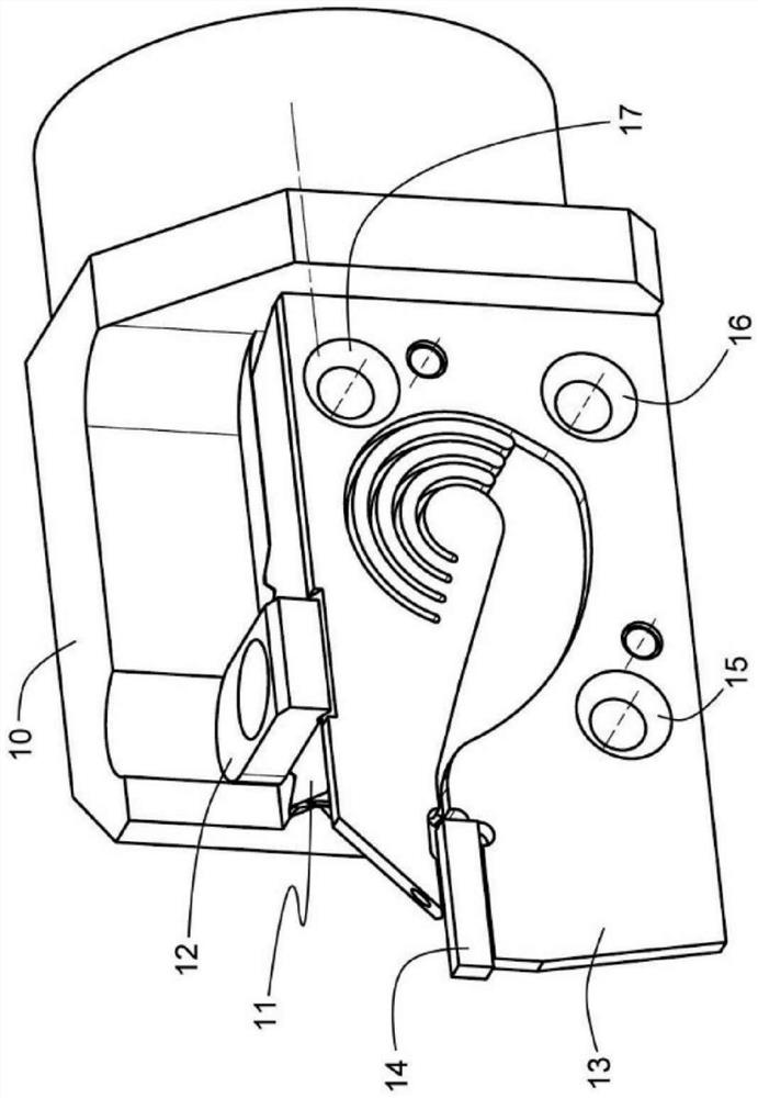
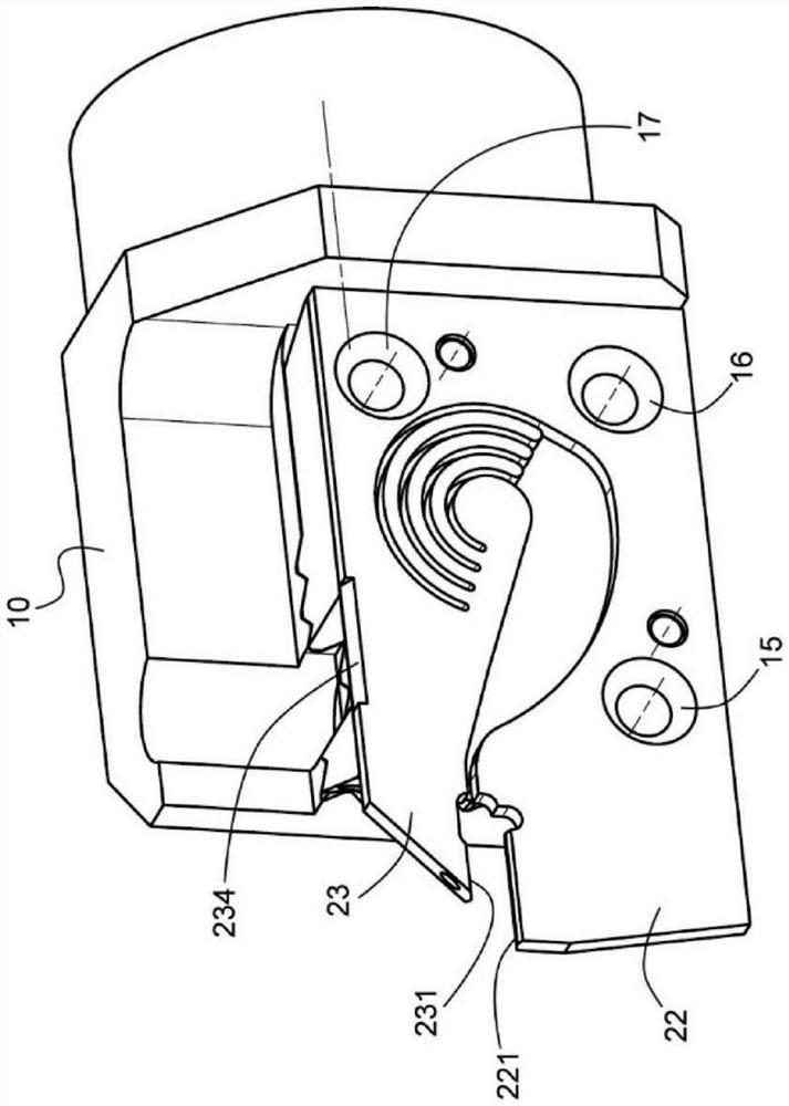
[0027] Basic tool holders are known in principle according to the prior art, and include connections on the power tool, for example HSK hollow tapers, and corresponding coolant feeds. In the present case, the complete tool consists of a basic tool support 10, a carrying box 11, and a clamping support 13, on which clamping jaws 12 are fastened and to which cutting inserts 14 are clamped. clamped into the bracket. The clamping bracket has three bores 15 , 16 , 17 including countersinks, through which a screw can be inserted with a countersink and used for screwing to the carrier box 11 . A slight offset of the holes 15 , 16 , 17 relative to the threaded holes in the carrier box can ensure, as is known in the prior art, that the clamping bracket when actuating the clamping screw is pulled into the desired end position.

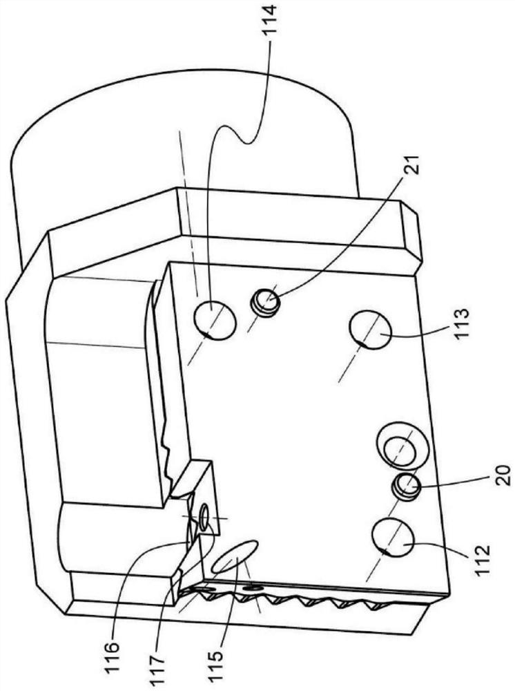
[0028] Other holes 18, 19 (see Figure 6 ) for ensuring the first positioning of the clamping bracket by the pins 20 , 21 protruding from the carrier box 11 ....


PUM


Abstract

The invention relates to a tool for machining, comprising a base support (10), a carrier box (11), a clamping jaw (12) and a clamping support (13), the clamping support comprising a receiving opening(25)for releasably clamping a cutting insert (14), the receiving opening being defined by a lower clamping jaw (22), an opposite upper clamping jaw (23) and a rear stop (24), a slot (28) and a widening (29) being connected in the rear region of the receiving opening next to the rear stop (24), wherein the upper clamping jaw (23) can be opened relative to the lower clamping jaw (22) by means of theformation of the slot and the widening. The tool is characterized in that at least one arc-shaped slot or a slot formed as an open polygonal curve is connected in the region of the upper part of thewidening, said slot extending at an angle of at least 120 degrees in a left-hand-bent manner when viewed from the front, the tool ensures sufficient stability during machining.

Description

technical field [0001] The invention relates to a tool comprising a basic support, a carrying box, clamping pliers and a clamping support comprising a receiving opening for releasably clamping a cutting blade, said The receiving opening is delimited by the lower clamping jaw, the upper clamping jaw opposite the lower clamping jaw and the rear stop, wherein the rear stop is located in the rear region of the receiving opening Adjacent thereto are slots and widenings, through which the upper clamping jaws can be opened relative to the lower clamping jaws. Background technique [0002] Such tools are required especially for cutting inserts for blanking and longitudinal turning as well as for cutting and parting processes on rotating workpieces. Cutting inserts that are subject to wear during the cutting process must be replaced at the latest when the required manufacturing accuracy during the cutting process is no longer ensured due to the wear. If the cutting edge breaks off ...

Claims


Application Information

Patent Timeline
IPC IPC(8): B23B27/16B23B27/10
CPCB23B27/10B23B27/1666B23B27/086B23B29/043B23B2250/12
Inventor J·奥古斯丁-佩亚J·魏施努尔
Owner ZCC CUTTING TOOLS EURO
Why Eureka
Try Eureka