Unlock instant, AI-driven research and patent intelligence for your innovation.

Current sensor

A current detector and current technology, applied in the direction of only measuring current, components of electrical measuring instruments, measuring current/voltage, etc., can solve problems such as unevenness, instability of resin, uneven filling amount or filling density, etc.

Pending Publication Date: 2021-01-05
TAMURA KK
View PDF1 Cites 0 Cited by
  • Summary
  • Abstract
  • Description
  • Claims
  • Application Information

AI Technical Summary

Problems solved by technology

[0004] However, as shown in the prior art described above, when the position of the core is fixed by the molding member filled in the box, due to the unevenness of the filling amount or filling density and the unevenness of the resin, the The position where the rear core is finally fixed is not constant, resulting in deviations in each individual product
In addition, if the fixing position of the core deviates, the position of the Hall element inserted into the gap in the gap will be unstable. Therefore, even if the magnetic flux under the same conditions is the same, the detection accuracy of the Hall element in each product will be lower. There will also be large deviations

Method used


Image

  • Current sensor
  • Current sensor
  • Current sensor

Examples


Embodiment Construction

[0031] Hereinafter, embodiments of the present invention will be described with reference to the drawings. In the following embodiments, a magnetic proportional current sensor is cited as an example of the current detector, but the present invention is not limited thereto, and may be a magnetic balance current sensor or a fluxgate current sensor.

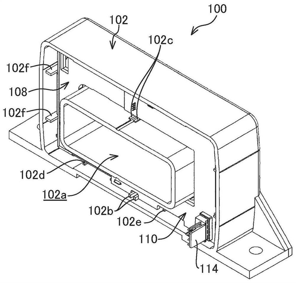
[0032] Figure 1A and Figure 1B It is a perspective view showing an assembled state of the current sensor 100 according to one embodiment. in addition, figure 2 and image 3 It is an exploded perspective view schematically showing the configuration of the current sensor 100 according to one embodiment. In addition, if shown from a different direction (180° opposite side) Figure 1A shown in the current sensor 100, then becomes Figure 1B stereogram. In addition, in figure 2 and image 3 , the viewing direction in the perspective view is reversed.

[0033] [overall composition]

[0034] Such as figure 2 and image 3 As...


PUM


Abstract

A current sensor (100) includes core members (104a, 104b) which form a converging path of a magnetic field generated by continuity of a current to be sensed by providing gaps (104c) in respective spaces between end surfaces facing each other in a plurality of sections to be disposed in an annular shape; a case body (102) which disposes and houses the core members (104a, 104b) in an annular shape;and a positioning member (108) which positions the core members (104a, 104b) at predetermined positions where the gaps (104c) are held in a specified distance by biasing the core members (104a, 104b)to each other in directions facing each other in the case body (102).

Description

technical field [0001] The present invention relates to a current detector that concentrates a magnetic field generated by conduction of a current to be detected to a core and detects a current. Background technique [0002] For example, conventionally, a publication (JP2012-068158A1) issued by the Japan Patent Office discloses the prior art of a current sensor in which a magnetic sensor is arranged in a gap formed in a ring-shaped core. In this current sensor, a container-shaped member is interposed between the cores accommodated in the case, and a resin molding member is filled into the case in a state where the opening end of the container-shaped member is exposed to the outside. The core is potted inside to secure the core in the desired position. [0003] In particular, in the prior art described above, the internal space of the container-shaped member interposed between the gaps of the cores is a space in which no resin molding member exists. Expansion or contraction...

Claims


Application Information

Patent Timeline
Patent Type & Authority Applications(China)
IPC IPC(8): G01R19/00G01R1/04G01R1/02
CPCG01R19/0092G01R1/0408G01R1/04G01R1/02G01R15/207G01R15/202
Inventor 桥本诚门马彰夫龙末洋余孔惠
Owner TAMURA KK