
Tank cover base ring production line and using method thereof
A production line and can lid technology, which is applied to the can lid base ring production line and its application field, and can solve the problems of difficult fixing of the inner ring and difficult operation
- Summary
- Abstract
- Description
- Claims
- Application Information
AI Technical Summary
Problems solved by technology
Method used
Image

Examples
Embodiment 1
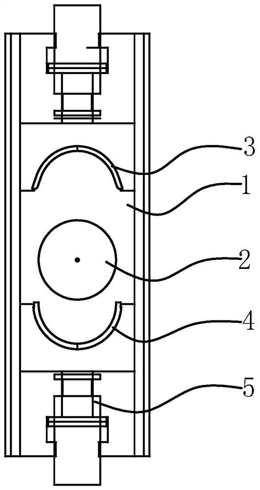
[0034]This embodiment provides a can end ring machine, the can end ring machine includes a first support frame, the first support frame is provided with a first platform 1, and the middle part of the first platform 1 is provided with a cylindrical Shaped first inner mold 2, the height of the first inner mold 2 is the same as the height of the iron plate to be processed. Both sides of the first inner mold 2 are respectively provided with a first left mold 3 and a first right mold 4, and the sides of the first left mold 3 and the first right mold 4 close to the first inner mold 2 are both A semicircular first semicircular groove is provided, and the first left mold 3 and the first right mold 4 are respectively provided with a first telescopic device 5 on a side away from the first inner mold 2, and the first The telescopic device 5 is used to drive the first left mold 3 and the first right mold 4 close to or away from the first inner mold 2; when the first left mold 3 and the fi...
Embodiment 2
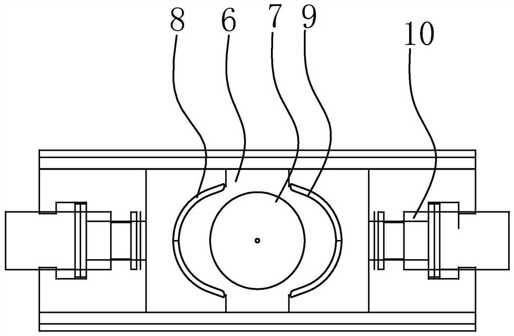
[0039] This embodiment provides a can lid base ring production line, the can lid base ring production line includes the can lid ring circular machine in the above-mentioned embodiment 1, and also includes an inner ring assembly machine; the inner ring assembly machine includes a second support frame , the second support frame is provided with a second platform 6, the middle part of the second platform 6 is provided with a cylindrical second inner mold 7, the height of the second inner mold 7 is lower than the iron plate to be treated It should be noted that the height of the second inner mold 7 is lower than the height of the iron plate to be processed, and is mainly used to place the inner ring; preferably, the height difference between the second inner mold 7 and the iron plate is the same as that of the inner ring are basically the same height. Both sides of the second inner mold 7 are respectively provided with a second left mold 8 and a second right mold 9, and the sides ...
Embodiment 3
[0044] This embodiment provides a method for using the can lid base ring production line in Embodiment 2. The method for using the can lid base ring production line includes the following steps:
[0045] The first step: prepare a strip-shaped iron plate, place the iron plate horizontally and vertically on the platform between the first left mold 3 or the first right mold 4 and the first inner mold 2 , the iron plate is perpendicular to the moving direction of the first left mold 3 and the first right mold 4;
[0046] Second step: start the first telescopic device 5 corresponding to the first left mold 3 or the first right mold 4, drive the first left mold 3 or the first right mold 4 to the first inner mold 2 Move closer; when the first left mold 3 or the first right mold 4 draws closer to the first inner mold 2, the iron plate is bent into a U shape;
[0047] The third step: start the first telescopic device 5 corresponding to the first right mold 4 or the first left mold 3, ...
PUM
 Abstract
Description
Claims
Application Information