Combustion drag reduction method and device applied to scramjet engine

A scramjet and engine technology, applied in ramjet engines, combustion methods, engine components, etc., can solve the problems of fuel flameout in the engine, affecting the normal use of the engine, etc., to reduce frictional resistance and reduce frictional resistance. Effect

Active Publication Date: 2021-02-19
CHINA AERODYNAMICS RES & DEV CENT
View PDF17 Cites 4 Cited by
  • Summary
  • Abstract
  • Description
  • Claims
  • Application Information

AI Technical Summary

Problems solved by technology

But it also has unavoidable disadvantages. When the working conditions of the engine change, due to the reduction of the flame stabilization measures such as the concave cavity, struts or support plates, it is likely that the fuel in the engine will stall, which will affect the normal use of the engine.

Method used


Image

  • Combustion drag reduction method and device applied to scramjet engine
  • Combustion drag reduction method and device applied to scramjet engine
  • Combustion drag reduction method and device applied to scramjet engine

Examples


Embodiment 1

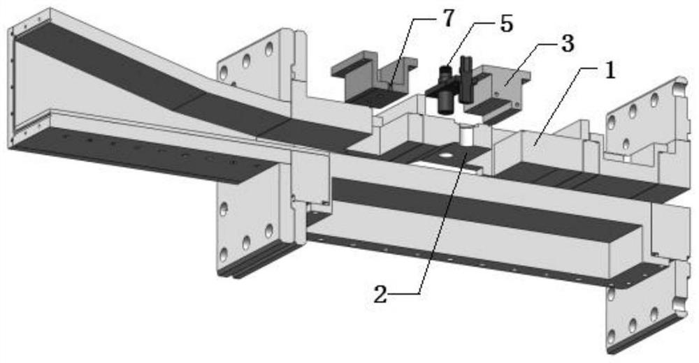
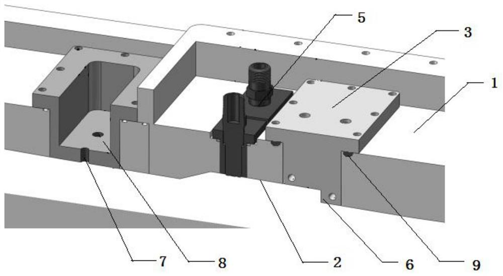
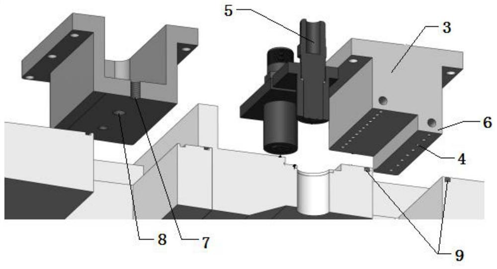
[0026] see Figure 1-4 , a combustion drag reduction method applied to scramjet engines, injecting gaseous hydrogen fuel into the concave cavity 2 of the scramjet flame stabilizer 1, using the spark plug 5 to realize forced ignition, so that the fuel can be burned stably; the fuel combustion changes The flow structure of the scramjet reduces the velocity near the wall of the scramjet, thereby reducing the velocity gradient near the wall of the scramjet and reducing the frictional resistance of the scramjet.

[0027] This embodiment is different from the traditional combustion drag reduction mechanism. The flow structure of the scramjet is changed by combustion, and the velocity gradient near the engine wall is reduced, thereby reducing the frictional resistance of the engine. The invention will change the current common understanding on the mechanism of combustion drag reduction, and enrich and perfect the mechanism of combustion drag reduction. However, the drag-reducing met...

Embodiment 2

[0032] In this embodiment, the engine model such as figure 1 As shown, the inlet interface of the isolation section of the engine model is 30mm×150mm, the overall length of the model is 1073mm, the size of the fuel injection block 3 is 140mm×80mm×60mm, the cavity 2 is 11mm deep and 121mm long. The model uses hydrogen as fuel, the fuel injection pressure is 1.5MPa, and the equivalence ratio is about 0.1. In non-combustion flow ( Figure 4 Schlieren diagram), when the supersonic gas flow flows through the cavity 2 area, an expansion wave structure is generated at the step of the cavity 2. The shear layer (B) at the lower part of the cavity 2 is in contact with the bottom of the cavity 2. When the high-speed air flow further flows through the slope of the rear edge of the cavity 2, an oblique shock wave system (C) is generated, which is connected with the bottom of the engine. The wall boundary layer interacts, and the oblique shock wave is reflected by the wall. A separation ...


PUM


Abstract

The invention relates to the technical field of scramjet engines, and discloses a combustion drag reduction method and device applied to a scramjet engine. Gaseous hydrogen fuel is injected into a concave cavity of a flame stabilizer of the scramjet engine, and forced ignition is achieved through a spark plug, so that the fuel is stably combusted. The flow structure of the scramjet engine is changed through fuel combustion, so that the speed near the wall surface of the scramjet engine is reduced, the speed gradient near the wall surface of the engine is reduced, and the frictional drag of thescramjet engine is reduced. Different from a traditional combustion drag reduction mechanism, the flow structure of the scramjet engine is changed, so that the speed gradient near the wall surface ofthe engine is reduced, and then the friction drag of the engine is reduced. The common understanding of the combustion drag reduction mechanism at present is changed through the method, and the combustion drag reduction mechanism is enriched and perfected.

Description

technical field [0001] The invention relates to the technical field of scramjet engines, in particular to a method and device for reducing combustion resistance of scramjet engines. Background technique [0002] Scramjet is the preferred propulsion system for hypersonic vehicles, especially at hypersonic cruise (Ma>5), it exhibits good specific impulse performance. Therefore, researchers around the world are still continuing to carry out research on scramjet related technologies, especially to improve the propulsion performance of scramjet and reduce the resistance of scramjet. [0003] There are many research aspects in the research of reducing resistance. The study found that the combustion of hydrogen fuel in the boundary layer near the wall can reduce the frictional resistance of the wall, and pointed out that the principle is due to the effect of film cooling (film cooling), that is: injected hydrogen The density is very low, which reduces the airflow density in the...

Claims


Application Information

Patent Timeline
Patent Type & Authority Applications(China)
IPC IPC(8): F02K7/10F02C7/22F23R3/20F23R3/28
CPCF02K7/10F02C7/22F23R3/20F23R3/28
Inventor 田野钟富宇蒋安林时文肖保国张弯洲邓维鑫李季李世豪孙光焱鲁玲张娜
Owner CHINA AERODYNAMICS RES & DEV CENT
Why Eureka
Try Eureka