Prismatic cavity blade tip for controlling leakage flow of movable blade tip of turbine

A prismatic and concave cavity technology, applied in the field of prismatic concave cavity blade tip, can solve the problem of different control effects, and achieve the effects of enhanced wearability, small clearance allowable value, and weight reduction.

Inactive Publication Date: 2018-08-17
HARBIN INST OF TECH
View PDF4 Cites 3 Cited by
  • Summary
  • Abstract
  • Description
  • Claims
  • Application Information

AI Technical Summary

Problems solved by technology

The most direct and effective way to control the gap flow is to reduce the gap value, but in order to avoid collision, contact and even damage to the components between the rotor blade and the casing, a reasonable gap value must be considered in the turbine design
The gap flow passive control technology widely studied now mainly includes tip / casing trimming, tip shroud, winglet, tip rib / groove, modern sealing structure, etc. Most of the research focuses on ensuring a certain gap value Effective measures should be taken to control the leakage flow, and the control effects of various gap flow control technologies will vary with specific objects, and there are corresponding deficiencies. Currently, the actual application of the technology is still limited.

Method used


Image

  • Prismatic cavity blade tip for controlling leakage flow of movable blade tip of turbine
  • Prismatic cavity blade tip for controlling leakage flow of movable blade tip of turbine
  • Prismatic cavity blade tip for controlling leakage flow of movable blade tip of turbine

Examples


Embodiment Construction

[0027] It should be noted that, in the case of no conflict, the embodiments of the present invention and the features in the embodiments can be combined with each other.

[0028] The invention will be described in detail below with reference to the accompanying drawings and examples.

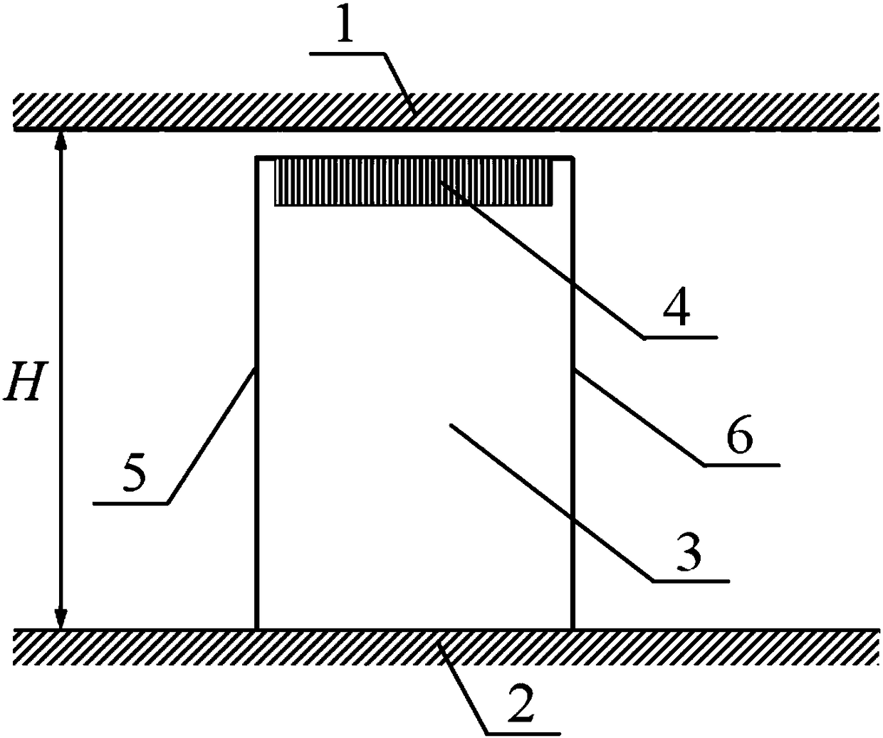
[0029] Such as figure 1 As shown, the present invention is applied in the turbine rotor blade, the turbine rotor blade 3 is installed on the hub 2, and the cascade flow channel is formed between the casing 1 and the hub 2, and 5 and 6 represent the leading edge line and the trailing edge of the rotor blade respectively Line, a number of prismatic concave cavities 4 are arranged at the blade tip of the turbine rotor blade 3 from the leading edge to the trailing edge position, and the distance between the turbine rotor blade 3 and the casing 1 is the clearance height.

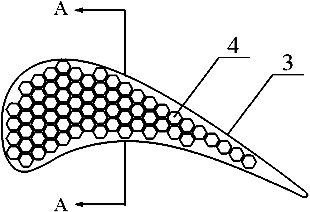
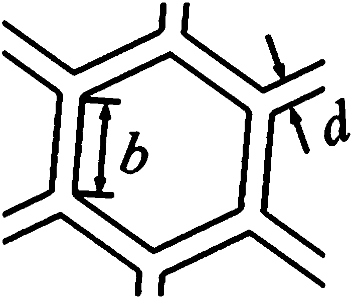
[0030] combine figure 2 with Figure 3a , Figure 3b , the specific arrangement of positive prism-shaped concave cavities on...


PUM


Abstract

The invention provides a prismatic cavity blade tip for controlling leakage flow of a movable blade tip of a turbine. At the blade tip of a movable blade of the turbine, a plurality of prismatic cavities are formed from the front edge to the tail edge of the movable blade of the turbine; and the ratio of the maximal depth h of the prismatic cavities to the height H of the movable blade of the turbine is 0.5%-4%. According to the prismatic cavity blade tip for controlling the leakage flow of the movable blade tip of the turbine provided by the invention, a part of leaking fluid which enters a clearance enters the prismatic cavities to form vortex in a rolling way; at one hand, the dynamic energy of the fluid in the clearance is dissipated; on the other hand, a jet flow stop effect is achieved on the fluid in the clearance above the cavities; and thus the aim of controlling the leakage flow of the blade tip of the turbine is realized; the leakage amount of the blade tip of the turbine isreduced; the size and strength of leakage vortex of the blade tip are reduced; leakage related loss of the turbine is reduced; the efficiency of the turbine is improved; and furthermore the prismaticcavity structure can reduce the weight of the blade of the turbine.

Description

technical field [0001] The invention belongs to the field of turbines, and in particular relates to a prismatic concave-cavity blade top for controlling the leakage flow of the blade tip of a turbine blade. Background technique [0002] As one of the key power components of the engine, the turbine is the key content in the engine design. The main research content of improving the performance of the turbine is to control the internal flow of the turbine to reduce the loss of the turbine and increase the power of the turbine. Turbine blade tip clearance leakage flow is one of the typical flows inside the turbine, which not only reduces the load on the blade tip, but also creates a complex vortex system that makes the flow in the end region more complicated. Studies have shown that the loss caused by the gap leakage flow in the end region of the turbine cascade is as high as the end region. 87% of the district's total losses. Especially in recent years, high-performance turbi...

Claims


Application Information

Patent Timeline
Patent Type & Authority Applications(China)
IPC IPC(8): F01D5/14
CPCF01D5/141F01D5/147
Inventor 陈浮俞建阳付云峰
Owner HARBIN INST OF TECH
Why Eureka
Try Eureka