Columnar workpiece paint spraying device for machining

A columnar workpiece, machining technology, applied in spray devices, liquid spray devices, spray booths, etc., can solve the problems of insufficient spray paint, inconvenient operation, etc., and achieve the effect of improving stability

Inactive Publication Date: 2021-02-23
李济存
View PDF0 Cites 0 Cited by
  • Summary
  • Abstract
  • Description
  • Claims
  • Application Information

AI Technical Summary

Problems solved by technology

[0004] Based on the technical problems of insufficient paint spraying and inconvenient operation in the existing paint spraying device when spraying the columnar workpiece, the present invention proposes a columnar workpiece paint spraying device for mechanical processing

Method used


Image

  • Columnar workpiece paint spraying device for machining
  • Columnar workpiece paint spraying device for machining
  • Columnar workpiece paint spraying device for machining

Examples


Embodiment 1

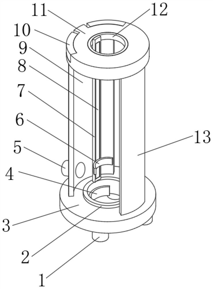
[0027] refer to Figure 1-4 , a columnar workpiece painting device for mechanical processing, comprising a first annular support plate 3 and a second annular support plate 11, the outer wall of the top side of the first annular support plate 3 is connected with an arc-shaped groove plate 9 by bolts, and the arc-shaped The top outer wall of the slot plate 9 is connected with the bottom side outer wall of the second annular support plate 11 by bolts, and the bottom outer wall of the arc slot plate 9 side is connected with the discharge pipe 5 by bolts, the second annular support plate 11 and the first The outer walls at both ends of one side of the annular support plate 3 are provided with first grooves, and the ends of the four first groove inner walls that are far away from each other are connected with support legs 10 through hinges, and the inner wall of the ring mouth of the second annular support plate 11 passes through An annular electric guide rail 12 is connected by bol...

Embodiment 2

[0035] refer to Figure 1-5 , a columnar workpiece painting device for mechanical processing, also includes a rotating rod 23 installed horizontally on the inner wall of the liquid spray pipe 14 through bearings, and the outer wall of the middle part of the rotating rod 23 is connected with a sheave 22 by bolts.

[0036] Working principle: when in use, by setting the rotating rod 23 and the sheave 22 in the liquid spray pipe 14, the sheave 22 can roll on the columnar workpiece, which reduces the frictional force and ensures that the liquid spray pipe 14 is compatible with the columnar workpiece. The close proximity of the workpiece improves the adequacy of the painting process.


PUM


Abstract

The invention belongs to the technical field of machining, and particularly relates to a columnar workpiece paint spraying device for machining. By aiming at the problems that when an existing paint spraying device sprays paint to a columnar workpiece, paint spraying is insufficient, and operation is inconvenient, the following scheme is provided, wherein the columnar workpiece paint spraying device comprises a first annular supporting plate and a second annular supporting plate, the outer wall of one side of the top of the first annular supporting plate is connected with an arc-shaped grooveplate through bolts, the outer wall of the top of the arc-shaped groove plate is connected with the outer wall of one side of the bottom of the second annular supporting plate through bolts, and the outer wall of the bottom of one side of the arc-shaped groove plate is connected with a discharging pipe through bolts. In the columnar workpiece paint spraying device for machining, the arc-shaped groove plate is arranged, the discharging pipe is arranged on the arc-shaped groove plate, and therefore when the device is horizontally placed, leaked paint can be recycled through the discharging groove plate and discharged from the discharging pipe, cleaning convenience of the device is guaranteed, and meanwhile paint can be recycled.

Description

technical field [0001] The invention relates to the technical field of mechanical processing, in particular to a painting device for columnar workpieces for mechanical processing. Background technique [0002] Machining refers to the process of changing the shape or performance of a workpiece through a mechanical device. According to the difference in processing methods, it can be divided into cutting processing and pressure processing, which refers to the whole process of making products from raw materials (or semi-finished products). For machine production, it includes transportation and storage of raw materials, production preparation, blank manufacturing, processing and heat treatment of parts, product assembly, debugging, painting and packaging, etc. [0003] In the process of mechanical processing, it is necessary to spray paint on the surface of the columnar workpiece. In the process of using the existing paint spraying device, a single spray head is used to spray pa...

Claims


Application Information

Patent Timeline
Patent Type & Authority Applications(China)
IPC IPC(8): B05B16/20B05B9/04B05B13/02B05B13/04B05B14/00B08B1/00B08B1/04
CPCB05B9/0403B05B13/0214B05B13/041B05B13/0426B08B1/005B08B1/04B05B14/00B05B16/20Y02P70/10
Inventor 李济存
Owner 李济存
Why Eureka
Try Eureka