Ship waste gas washing device

A technology for washing waste gas and ships, which is applied in the separation of dispersed particles, chemical instruments and methods, separation methods, etc., and can solve the problems of large space occupation, uneven distribution of washing liquid, and uneven liquid distribution.

Pending Publication Date: 2021-04-20
NINGBO UNIV
View PDF5 Cites 0 Cited by
  • Summary
  • Abstract
  • Description
  • Claims
  • Application Information

AI Technical Summary

Problems solved by technology

Both have their own advantages and disadvantages. The advantage of the spray scrubber is that the smoke resistance drop is small. The disadvantage is that the liquid-gas ratio is high and the pump consumption is large, especially when the load is low. In order to ensure the spray coverage and nozzle atomization quality, The liquid-gas ratio is higher, and the pump consumption per unit of flue gas treatment capacity is greater. Second, the spray washing area takes up a lot of space, with as many as 4 to 5 spray layers, and the spray washing area is as high as 6 meters to 8 meters.
The advantages of the packed scrubber are low liquid-to-gas ratio, low pump consumption, and strong adaptability to load

Method used


Image

  • Ship waste gas washing device
  • Ship waste gas washing device
  • Ship waste gas washing device

Examples


Embodiment 1

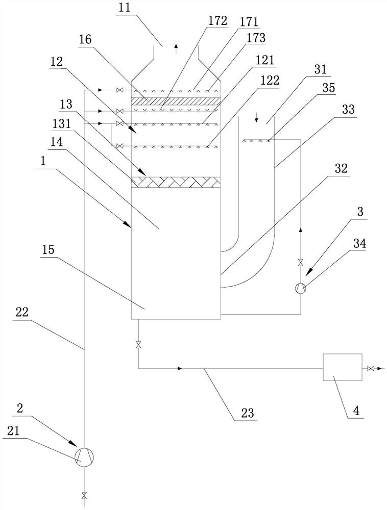
[0026] A kind of ship waste gas scrubbing device that present embodiment proposes, such as figure 1 As shown, it is composed of a washing tower 1, a washing liquid supply and drainage system 2, and a ship exhaust gas cooling system 3. The top of the washing tower 1 is provided with a ship exhaust gas outlet 11, and the washing tower 1 is provided with a spray layer washing area 12 and a packing layer. Washing area 13, the packing layer washing area 13 is located below the spray layer washing area 12, and the space below the packing layer washing area 13 in the washing tower 1 is divided into a ship exhaust gas cooling area 14 and a cooling liquid pool 15 from top to bottom (the cooling liquid pool 15 is built-in), the supply part of the washing liquid supply and drainage system 2 provides washing liquid for the spray layer washing area 12, and the discharge part of the washing liquid supply and drainage system 2 discharges the washing waste water, and the ship waste gas cooling...

Embodiment 2

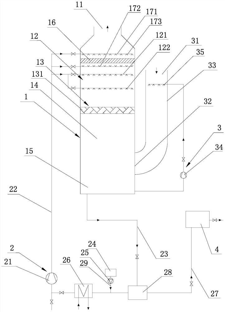
[0032] A kind of ship waste gas scrubbing device that present embodiment proposes, such as figure 2 As shown, the internal structure of the scrubber 1 and the structure of the ship exhaust gas cooling system 3 are the same as the ship exhaust gas scrubber of Embodiment 1, the difference lies in the structure of the washing liquid supply and drainage system 2, the washing liquid supply and drainage system 2 is external, The supply part of the cleaning solution supply and drainage system 2 includes a fresh lye storage tank 24, a metering pump 25, an lye cooler 26, a cleaning solution pump 21, and a cleaning solution main pipe 22, and the discharge part of the cleaning solution supply and drainage system 2 includes spent lye Discharging pipe 27, the supply part and the discharge part of washing liquid supply and drainage system 2 share washing waste water outlet pipe 23 and lye buffer tank 28, and the inlet of washing waste water outlet pipe 23 is connected with the bottom of was...

Embodiment 3

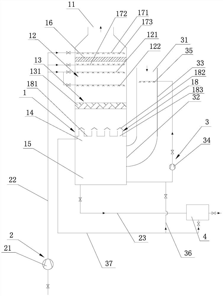
[0034] A kind of ship waste gas scrubbing device that present embodiment proposes, such as image 3 As shown, the internal structure of the washing tower 1 is the same as that of the ship exhaust gas scrubbing device in Embodiment 1, the difference lies in the structure of the ship exhaust gas cooling system 3 and the washing liquid supply and discharge system 2 . The exhaust gas cooling area 14 of the ship is provided with a ventilating liquid blocker 18 which allows the exhaust gas from the ship to pass from bottom to top and prevents the washing liquid from passing through, and the washed liquid falls on the venting liquid blocker 18; Cooler 33, external coolant pump 34, external coolant replenishment pipe 36, built-in coolant pool 15, ship exhaust gas inlet 31 is arranged on the top of cooler 33, and exhaust gas inlet 32 ​​is arranged on cooler 33 At the end of the cooler 33, a plurality of coolant nozzles 35 for atomizing coolant are uniformly arranged in the cooler 33. T...


PUM

PropertyMeasurementUnit
Thicknessaaaaaaaaaa

Abstract

The invention discloses a ship waste gas washing device which is composed of a washing tower, a washing liquid supply and discharge system and a ship waste gas cooling system, a ship waste gas outlet is formed in the top of the washing tower, and a spraying layer washing area, a packing layer washing area and a ship waste gas cooling area are sequentially arranged in the washing tower from top to bottom. A supply part of the washing liquid supply and discharge system provides washing liquid for the spraying layer washing area, a discharge part of the washing liquid supply and discharge system discharges washing wastewater, and the ship waste gas cooling system is provided with a ship waste gas inlet; ship waste gas introduced from the ship waste gas inlet is cooled by cooling liquid provided by the ship waste gas cooling system, enters the ship waste gas cooling area and then flows back from bottom to top; meanwhile, washing liquid provided by the supply part of the washing liquid supply and discharge system uniformly passes through the spraying layer washing area and the packing layer washing area in sequence to be in contact with ship waste gas flowing reversely from bottom to top to wash the ship waste gas, and the washed ship waste gas is discharged through a ship waste gas outlet; the invention has the advantage that low-resistance, low-consumption and high-efficiency washing can be realized.

Description

technical field [0001] The invention relates to a ship waste gas treatment technology, in particular to a ship waste gas washing device. Background technique [0002] With the continuous development of international shipping, the number of global ships is increasing year by year. Since most ships use heavy fuel oil (HFO) with high sulfur content and low cost as fuel, the exhaust gas contains a large amount of sulfur oxides (SO X ), nitrogen oxides (NOx) and particulate matter (PM), which have caused very serious pollution to the atmosphere. Therefore, the International Maritime Organization (IMO) has promulgated a global "sulfur limit order", requiring that from January 01, 2020 the global The mass fraction of sulfur in fuel oil used by ships is ≤0.5%. Choosing low-sulfur fuel oil is the simplest and most effective way to deal with the "sulfur limit order", but the price difference between high and low-sulfur fuel oil is large, and the cost of shipowners will increase grea...

Claims


Application Information

Patent Timeline
IPC IPC(8): B01D53/92B01D53/50
Inventor 杨国华况敏徐争光吴林
Owner NINGBO UNIV
Why Eureka
Try Eureka