
A fiber optic gyroscope temperature compensation method, device, electronic equipment and storage medium

A technology of fiber optic gyroscope and temperature compensation, which is applied in the direction of measuring devices, instruments, etc., can solve the problems of gyroscope temperature drift, complex algorithm, unfavorable engineering implementation, etc., and achieve the effect of effective temperature drift

Active Publication Date: 2022-03-29
HUBEI SANJIANG AEROSPACE WANFENG TECH DEV
View PDF5 Cites 0 Cited by
  • Summary
  • Abstract
  • Description
  • Claims
  • Application Information

AI Technical Summary

Problems solved by technology

The neural network model has great advantages in terms of accuracy, but its algorithm is complex, which is not conducive to engineering implementation
Most of the existing polynomial models only consider the influence of the current temperature of the gyroscope, but the temperature drift of the fiber optic gyroscope is not only related to the current temperature, but also has a greater relationship with the previous temperature of the gyroscope, and the closer the forward temperature is to the current temperature. The greater the influence of gyro temperature drift

Method used


Image

  • A fiber optic gyroscope temperature compensation method, device, electronic equipment and storage medium
  • A fiber optic gyroscope temperature compensation method, device, electronic equipment and storage medium
  • A fiber optic gyroscope temperature compensation method, device, electronic equipment and storage medium

Examples


Embodiment approach

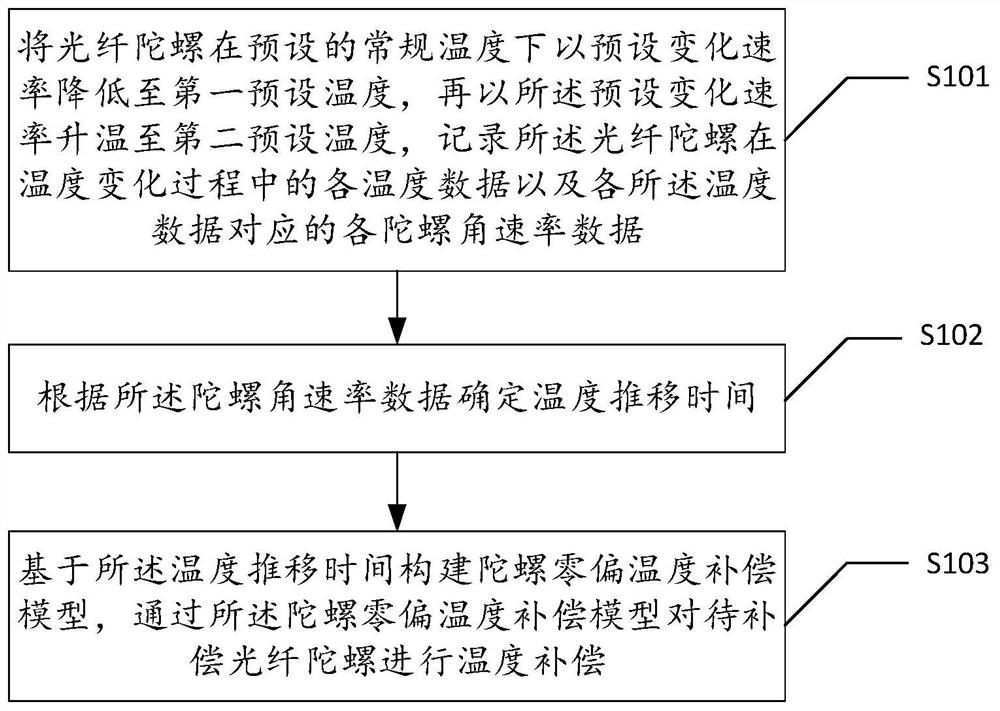
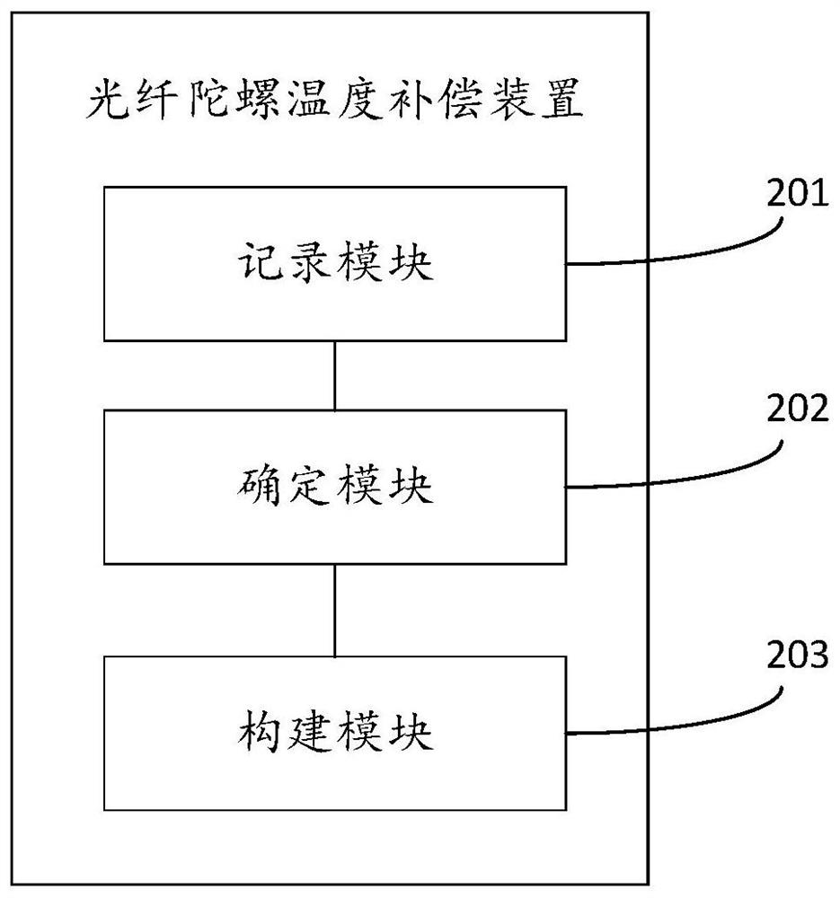
[0068] As an implementable manner, the recording module 201 includes:

[0069] An acquisition unit, configured to obtain current temperature data of the fiber optic gyroscope and gyroscope angular rate data corresponding to the temperature data when the temperature of the fiber optic gyroscope changes per unit time at the preset rate of change;

[0070] The recording unit is used to record all the temperature data and gyroscope angular rate data during the temperature change process.

[0071] As an implementable manner, the determining module 202 is specifically configured to:

[0072] Converting each of the gyroscope angular rates into several time series at different time intervals;

[0073] Calculating the standard deviation and mean of each of said time series in turn;

[0074] calculating a coefficient of variation for each of the time series based on the standard deviation and the mean, respectively;

[0075] The time interval corresponding to the time series with the...


PUM


Abstract

The invention discloses a fiber optic gyroscope temperature compensation method, device, electronic equipment and storage medium. The method includes: lowering the fiber optic gyroscope to a first preset temperature at a preset rate of change at a preset conventional temperature, and then heating up to a second preset temperature at a preset rate of change, and recording the temperature of the fiber optic gyroscope Each temperature data in the change process and each gyro angular rate data corresponding to each said temperature data; determine the temperature transition time according to the gyro angular rate data; build a gyro zero bias temperature compensation model based on the temperature transition time, through the The gyroscope zero bias temperature compensation model performs temperature compensation on the optical fiber gyroscope to be compensated. The invention realizes the consideration of the influence of the previous temperature of the gyroscope, and constructs a temperature compensation model through the temperature interval difference of several temperature intervals on the time axis, which can effectively compensate the temperature drift of the gyroscope.

Description

technical field [0001] The present application relates to the technical field of inertial positioning and orientation, and in particular, relates to a fiber optic gyroscope temperature compensation method, device, electronic equipment and storage medium. Background technique [0002] The fiber optic gyroscope is an angular rate sensor based on the Sagnac effect. Due to its low cost, simple process, high reliability, and strong shock and vibration resistance, its application prospects have attracted much attention and it has become one of the mainstream sensors. However, the main components that make up the fiber optic gyroscope, such as fiber optic rings and light sources, are more sensitive to temperature, which causes the output of the fiber optic gyroscope to be greatly affected by temperature, and the gyroscope output drifts greatly with temperature changes, which reduces the measurement accuracy of the fiber optic gyroscope. Therefore, temperature drift compensation for...

Claims


Application Information

Patent Timeline
Patent Type & Authority Patents(China)
IPC IPC(8): G01C25/00
CPCG01C25/005
Inventor 左庆张书文刘亦男曹海波吕振宇郭梦凡余霞
Owner HUBEI SANJIANG AEROSPACE WANFENG TECH DEV
Learn More