Method and device used in user equipment and base station for wireless communication

A technology for user equipment and wireless communication, applied in the field of transmission of broadcast signals on unlicensed spectrum, which can solve the problem that licensed spectrum is difficult to meet the demand of traffic volume, and achieves the improvement of transmission flexibility, transmission flexibility and transmission opportunity. Effect

Pending Publication Date: 2021-06-04
SHANGHAI LANGBO COMM TECH CO LTD
View PDF0 Cites 0 Cited by
  • Summary
  • Abstract
  • Description
  • Claims
  • Application Information

AI Technical Summary

Problems solved by technology

[0006] In the traditional 3GPP (3rd Generation Partner Project, 3rd Generation Partnership Project) LTE (Long-term Evolution, long-term evolution) system, data transmission can only occur on the licensed spectrum. However, with the rapid increase of traffic, especially In some urban areas, licensed spectrum may be difficult to meet traffic demands

Method used


Image

  • Method and device used in user equipment and base station for wireless communication
  • Method and device used in user equipment and base station for wireless communication
  • Method and device used in user equipment and base station for wireless communication

Examples


Embodiment 1

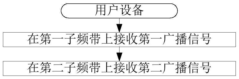
[0088] Embodiment 1 illustrates the flow chart of the first broadcast signal, as shown in the attached figure 1 shown.

[0089] In Embodiment 1, the user equipment in this application receives a first broadcast signal on a first sub-band, and receives a second broadcast signal on a second sub-band; the first broadcast signal includes a first type of synchronization signal and a first-type information block; the third broadcast signal transmitted on the second sub-band includes a first-type synchronization signal and a first-type information block, and the first-type information block included in the first broadcast signal Among the information blocks and the first-type information blocks included in the third broadcast signal, only the first-type information blocks included in the first broadcast signal are applied to the second broadcast signal.

[0090] As a sub-embodiment, the first type of synchronization signal includes at least one of PSS (Primary Synchronization Signal...

Embodiment 2

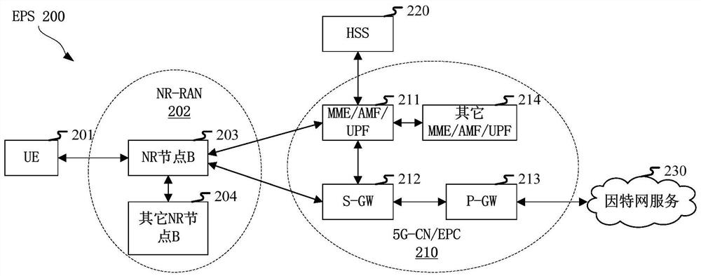
[0139] Embodiment 2 illustrates the schematic diagram of network architecture, as attached figure 2 shown.

[0140] Embodiment 2 illustrates a schematic diagram of a network architecture according to the present application, as attached figure 2 shown. figure 2It is a diagram illustrating NR 5G, LTE (Long-Term Evolution, long-term evolution) and LTE-A (Long-Term Evolution Advanced, enhanced long-term evolution) system network architecture 200 . The NR 5G or LTE network architecture 200 may be referred to as an EPS (Evolved Packet System, Evolved Packet System) 200 by some other suitable term. EPS 200 may include one or more UE (User Equipment, user equipment) 201, NG-RAN (next generation radio access network) 202, 5G-CN (5G-CoreNetwork, 5G core network) / EPC (Evolved Packet Core, Evolved Packet Core) 210 , HSS (Home Subscriber Server, Home Subscriber Server) 220 and Internet Service 230 . The EPS may be interconnected with other access networks, but these entities / interf...

Embodiment 3

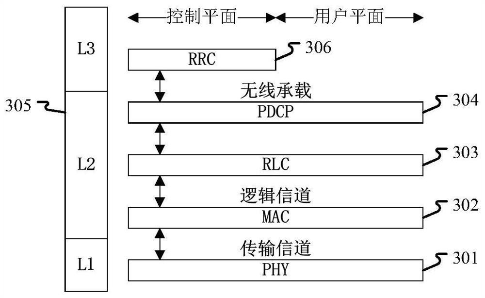
[0153] Embodiment 3 shows a schematic diagram of an embodiment of a wireless protocol architecture of a user plane and a control plane according to the present application, as shown in the attached image 3 shown.

[0154] attached image 3 is a schematic diagram illustrating an embodiment of a radio protocol architecture for a user plane and a control plane, image 3 The radio protocol architecture for user equipment (UE) and base station equipment (gNB or eNB) is shown in three layers: layer 1, layer 2 and layer 3. Layer 1 (L1 layer) is the lowest layer and implements various PHY (Physical Layer) signal processing functions. The L1 layer will be referred to herein as PHY 301 . Layer 2 (L2 Layer) 305 is above PHY 301 and is responsible for the link between UE and gNB through PHY 301 . In the user plane, the L2 layer 305 includes MAC (Medium Access Control, Media Access Control) sublayer 302, RLC (Radio LinkControl, Radio Link Layer Control Protocol) sublayer 303 and PDCP ...


PUM


Abstract

The invention discloses a method and a device in user equipment and a base station used for wireless communication. The user equipment receives a first broadcast signal on the first sub-band, and receives a second broadcast signal on a second sub-band; the first broadcast signal comprises a first type of synchronization signal and a first type of information block; a third broadcast signal transmitted on the second sub-band comprises a first type of synchronization signal and a first type of information block; only the first type information block included in the first broadcast signal in the first type information block included in the first broadcast signal and the first type information block included in the third broadcast signal is applied to the second broadcast signal. According to the application, the second broadcast signal is transmitted on the second sub-band through the design, and transmission of part of broadcast signals corresponding to one frequency band on the other frequency band is realized, so that the flexibility of broadcast signal transmission is improved, and the overall performance of the system is improved.

Description

[0001] This application is a divisional application of the following original application: [0002] --The filing date of the original application: 2018.01.11 [0003] --Application number of the original application: 201810025081.9 [0004] --The name of the invention of the original application: a user equipment used in wireless communication, a method and a device in a base station technical field [0005] The present application relates to a transmission method and device in a wireless communication system, in particular to a transmission method and device for a broadcast signal on an unlicensed spectrum (Unlicensed Spectrum). Background technique [0006] In the traditional 3GPP (3rd Generation Partner Project, 3rd Generation Partnership Project) LTE (Long-term Evolution, long-term evolution) system, data transmission can only occur on the licensed spectrum. However, with the rapid increase of traffic, especially In some urban areas, licensed spectrum may be difficult ...

Claims


Application Information

Patent Timeline
Patent Type & Authority Applications(China)
IPC IPC(8): H04W72/00H04W72/04H04W4/06H04L5/00
CPCH04W4/06H04W72/0453H04W72/0446H04L5/0053H04L5/0048H04W72/30
Inventor 蒋琦张晓博
Owner SHANGHAI LANGBO COMM TECH CO LTD
Why Eureka
Try Eureka