Method and device in UE and base station for wireless communication

a wireless communication and wireless communication technology, applied in the field of transmission methods and devices in wireless communication systems, can solve problems such as the inability the based on lte v2v, and the inability to solve the problem of how to meet the requirements of burst data services, and achieve the effect of increasing the possibility of transmission

Active Publication Date: 2021-07-13
HONOR DEVICE CO LTD
View PDF5 Cites 0 Cited by
  • Summary
  • Abstract
  • Description
  • Claims
  • Application Information

AI Technical Summary

Benefits of technology

[0012]In one embodiment, in the above method, time-frequency resources not available for the second-type transmission are reserved to the first-type transmission. Compared with conventional LTE V2V, the above method can increase opportunities of transmission.
[0013]In one embodiment, the above method reduces latency by using short-term monitoring.
[0014]In one embodiment, the above method reduces false alarm probability by using channel decoding.
[0064]In one embodiment, compared with conventional schemes, the disclosure has the following advantages.
[0066]In one embodiment, the above method reduces latency by using short-term monitoring.
[0067]In one embodiment, the above method reduces false alarm probability by using channel decoding.

Problems solved by technology

The inventor finds through researches that the channel sensing in LTE V2V is based on long-term measurement and is not beneficial for burst data services.
Therefore, how to meet the requirements of burst data services is a problem to be solved.

Method used


Image

  • Method and device in UE and base station for wireless communication
  • Method and device in UE and base station for wireless communication
  • Method and device in UE and base station for wireless communication

Examples


embodiment 1

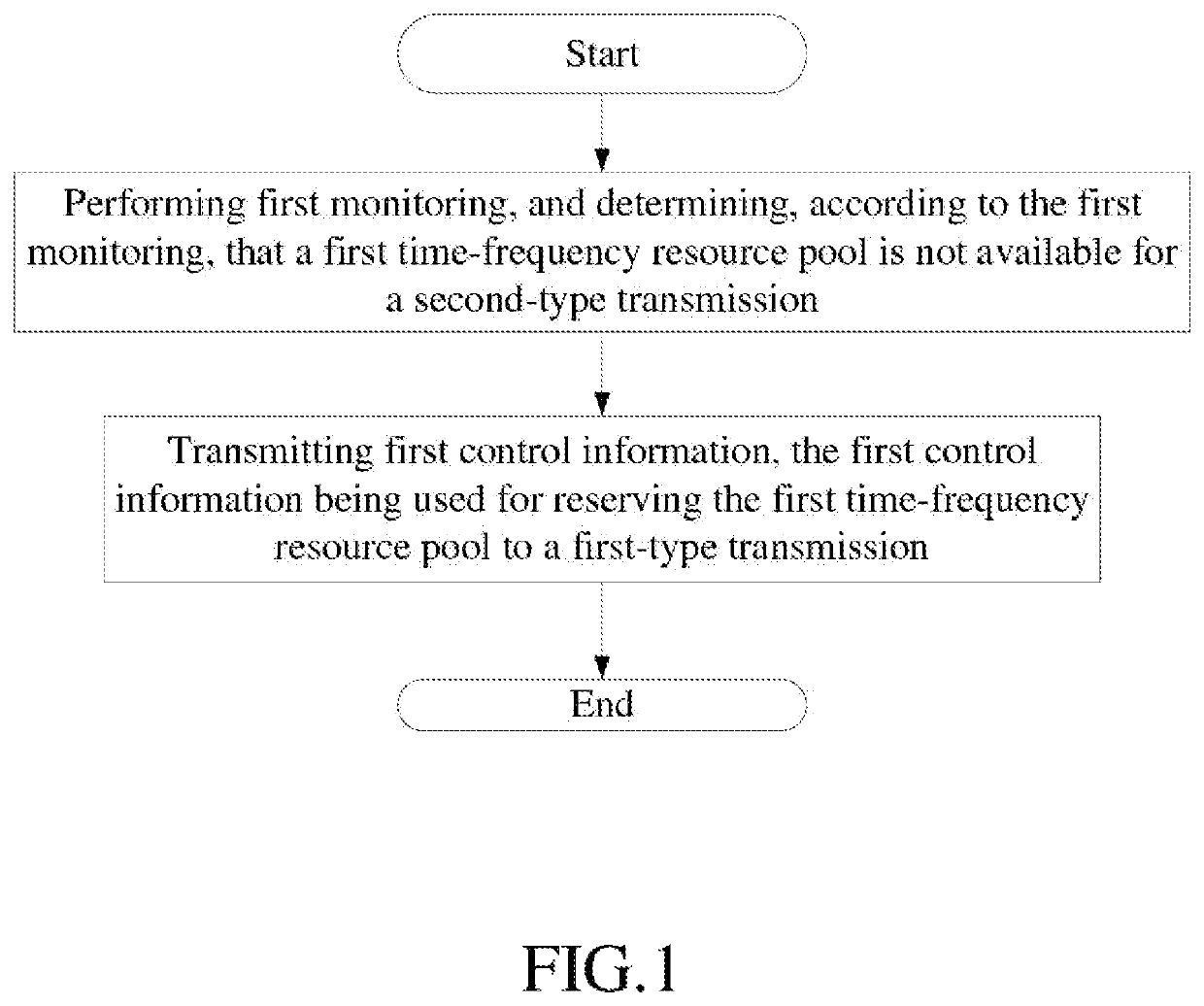
[0085]Embodiment 1 illustrates an example of a flowchart of processing of a first node, as shown in FIG. 1.

[0086]In Embodiment 1, the first node first performs first monitoring, and determines, according to the first monitoring, that a first time-frequency resource pool is not available for a second-type transmission, and then transmits first control information, the first control information being used for reserving the first time-frequency resource pool to a first-type transmission.

[0087]In Embodiment 1, the first monitoring belongs to first-type monitoring; for the first-type transmission and the second-type transmission, second-type monitoring is only used for determining whether the first-type transmission can be performed; and the first-type monitoring is long-term while the second-type monitoring is short-term.

[0088]In one embodiment, the phrase that the first-type monitoring is long-term while the second-type monitoring is short-term includes: time resources occupied by the ...

embodiment 2

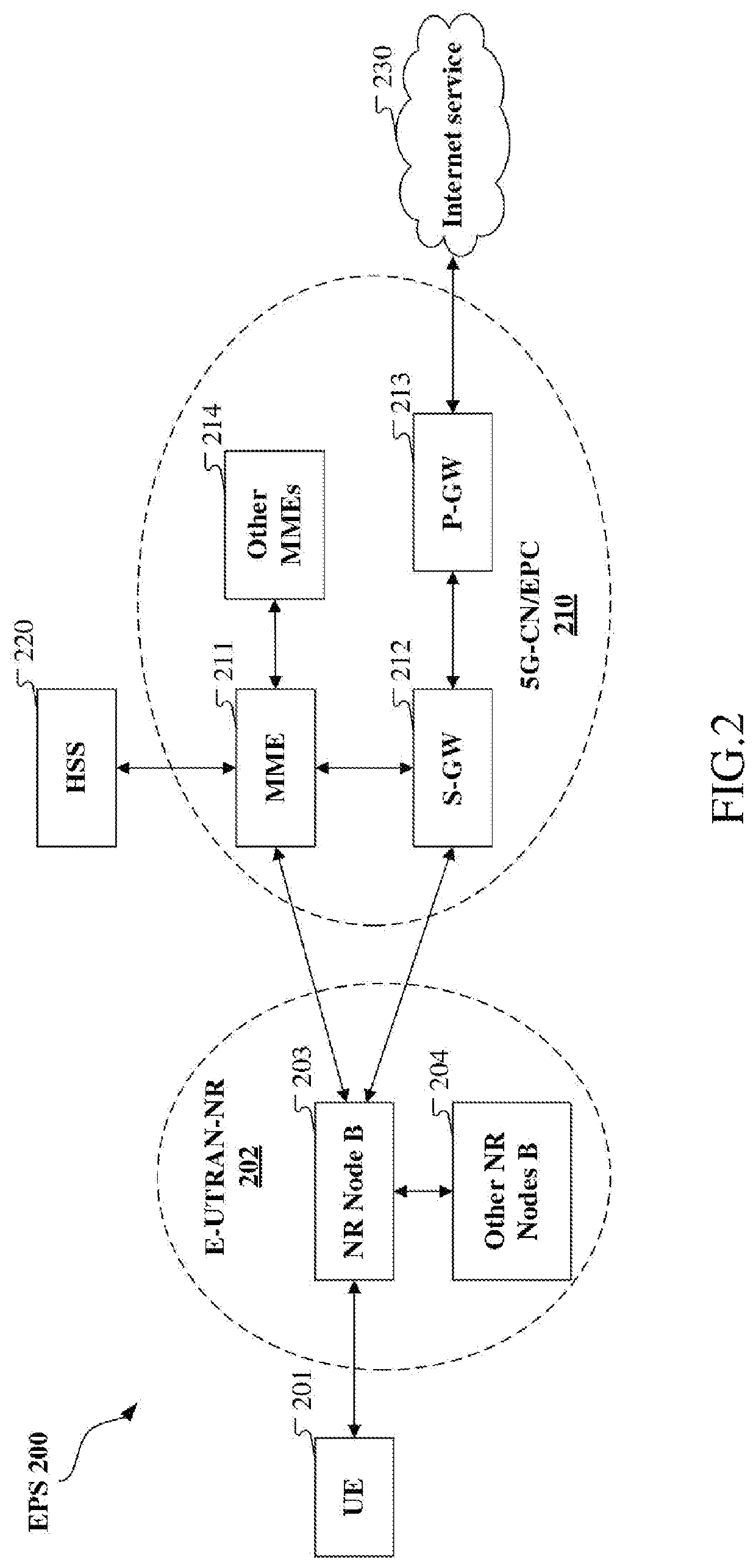
[0121]Embodiment 2 illustrates an example of a diagram of a network architecture, as shown in FIG. 2.

[0122]FIG. 2 illustrates a network architecture 200 of Long-Term Evolution (LTE), Long-Term Evolution Advanced (LTE-A) and future 5G systems. The LTE network architecture 200 may be called an Evolved Packet System (EPS) 200. The EPS 200 may include one or more UEs 201, an Evolved UMTS Terrestrial Radio Access Network-New Radio (E-UTRAN-NR) 202, a 5G-Core Network / Evolved Packet Core (5G-CN / EPC) 210, a Home Subscriber Server (HSS) 220 and an Internet Service 230. Herein, the UMTS represents Universal Mobile Telecommunication System. The EPS may be interconnected with other access networks. For simple description, the entities / interfaces are not shown. As shown in FIG. 2, the EPS provides packet switching services. Those skilled in the art are easy to understand that various concepts presented throughout the present disclosure can be extended to networks providing circuit switching serv...

embodiment 3

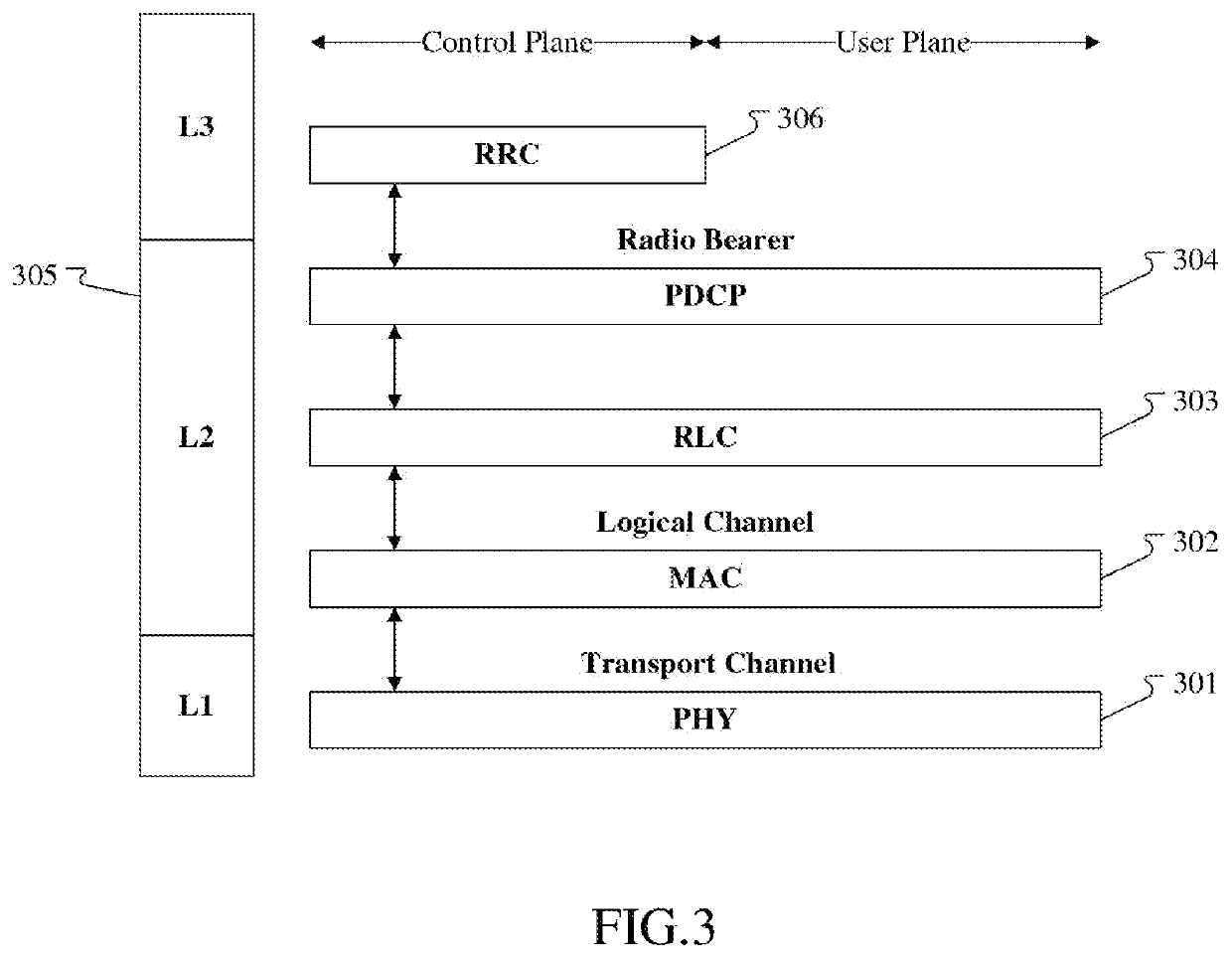
[0130]FIG. 3 is illustrates an example of a diagram of an embodiment of a radio protocol architecture of a user plane and a control plane, as shown in FIG. 3.

[0131]FIG. 3 is a diagram of an embodiment of a radio protocol architecture of a user plane and a control plane. In FIG. 3, the radio protocol architecture of a UE and a gNB is represented by three layers, which are a Layer 1, a Layer 2 and a Layer 3 respectively. The Layer 1 (L1 layer) is the lowest layer and implements various PHY (physical layer) signal processing functions. The L1 layer will be referred to herein as the PHY 301. The Layer 2 (L2 layer) 305 is above the PHY 301, and is responsible for the link between the UE and the gNB over the PHY 301. In the user plane, the L2 layer 305 includes a Medium Access Control (MAC) sublayer 302, a Radio Link Control (RLC) sublayer 303, and a Packet Data Convergence Protocol (PDCP) sublayer 304, which are terminated at the gNB on the network side. Although not shown, the UE may in...


PUM


Abstract

The disclosure provides a method and a device in a User Equipment (UE) and a base station for wireless communication. In one embodiment, a first node performs first monitoring, determines, according to the first monitoring, that a first time-frequency resource pool is not available for a second-type transmission, and transmits first control information, the first control information being used for reserving the first time-frequency resource pool to a first-type transmission; wherein the first monitoring belongs to first-type monitoring; for the first-type transmission and the second-type transmission, second-type monitoring is only used for determining whether the first-type transmission can be performed; and the first-type monitoring is long-term while the second-type monitoring is short-term. The disclosure increases opportunities of transmission, thus improves efficiency of transmission and utilization of spectrum.

Description

CROSS-REFERENCE TO RELATED APPLICATION[0001]This application claims the priority benefit of Chinese Patent Application Serial Number 201811306089.9, filed on Nov. 5, 2018, the full disclosure of which is incorporated herein by reference.BACKGROUNDTechnical Field[0002]The disclosure relates to transmission methods and devices in wireless communication systems, and in particular to a method and a device supporting channel monitoring.Related Art[0003]In 3rd Generation Partner Project (3GPP) Long Term Evolution (LTE) systems, Vehicle to Vehicle (V2V) communication is standardized. In LTE V2V, channel sensing is used for judging whether one Physical Sidelink Control Channel (PSCCH) can be used for V2V transmission.[0004]In 3GPP New Radio (NR) systems, discussions about V2V are ongoing.SUMMARY[0005]The inventor finds through researches that the channel sensing in LTE V2V is based on long-term measurement and is not beneficial for burst data services. Therefore, how to meet the requirement...

Claims


Application Information

Patent Timeline
Patent Type & Authority Patents(United States)
IPC IPC(8): H04W72/04
CPCH04W72/044H04W72/0406H04W24/02H04W28/26H04W72/0446H04W72/0453H04L5/0007H04L5/0048H04L5/0055H04L1/004H04W72/20H04W74/0808Y02D30/70
Inventor ZHANG, XIAOBOYANG, LIN
Owner HONOR DEVICE CO LTD
Why Eureka
Try Eureka