Liquid atomization device

A liquid atomization and liquid technology, applied in the field of atomizers, can solve the problem of inconvenient movement of liquid atomization devices

Inactive Publication Date: 2021-07-23
SHENZHEN IJOY TECH CO LTD
View PDF4 Cites 0 Cited by
  • Summary
  • Abstract
  • Description
  • Claims
  • Application Information

AI Technical Summary

Problems solved by technology

[0003] In view of the above-mentioned related technologies, the inventor believes that the atomizing core of the current liquid atomizer is directly immersed in the liquid. At this time, during the movement of the liquid atomizing device, the internal liquid is easily connected to the atomizing core. out of the atomizing tube, causing inconvenience in the movement of the liquid atomizing device

Method used


Image

  • Liquid atomization device
  • Liquid atomization device
  • Liquid atomization device

Examples


Embodiment Construction

[0031] The application will be described in further detail below in conjunction with the accompanying drawings.

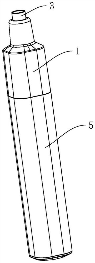
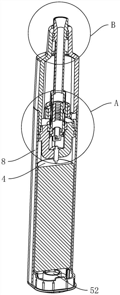
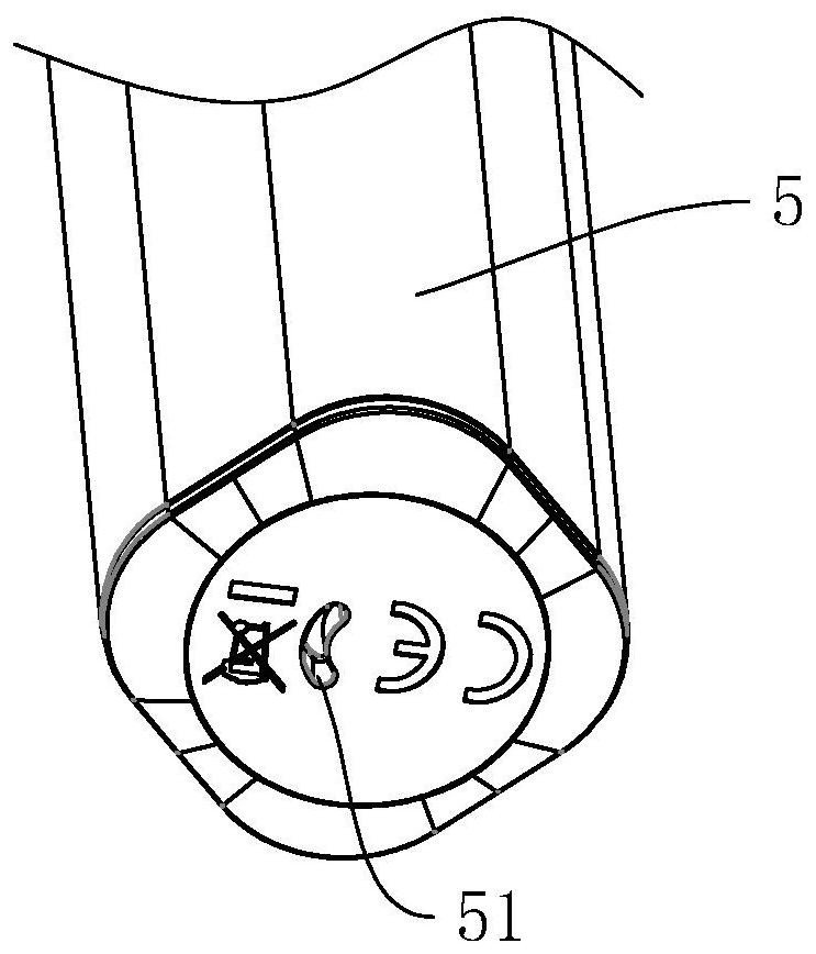
[0032] A liquid atomization device disclosed in the present application, such as figure 1 with figure 2 As shown, it includes a liquid chamber 1 with openings at both ends, an atomizing core 2 installed in the liquid chamber 1, an air guide tube 3 coaxially connected to the atomizing core 2, and a power supply for the atomizing core 2 connected to the liquid chamber 1 The cell 4. The opening at one end of the liquid chamber 1 is sleeved with a housing 5 with an opening at one end. The battery cell 4 is arranged in the housing 5, and the end surface of the housing 5 away from the liquid chamber 1 is provided with an air inlet 51 communicating with its inner cavity (see image 3 ), a flow sensor 52 is clamped in the inner cavity of the housing 5 close to the air inlet 51, and the flow sensor 52 is electrically connected to the battery cell 4 to control the on-off ...


PUM


Abstract

The application relates to a liquid atomization device which comprises a liquid bin, an atomization core, an air guide pipe and a battery cell, the end, away from the atomization core, of the air guide pipe penetrates through the liquid bin and is located outside the liquid bin, the inner wall, at the extending position of the air guide pipe, of the liquid bin is attached to the outer wall of the air guide pipe, and the air guide pipe slides along the axis of the liquid bin, the atomization core is electrically connected with the battery cell, an atomization pipe is coaxially arranged outside the atomization core, one end of the atomization pipe is coaxially connected with the air guide pipe, a first liquid inlet hole is formed in the outer wall of the atomization pipe in the circumferential direction, a sealing sleeve is arranged in the liquid bin, and the inner wall of the sealing sleeve is attached to the outer wall of the atomization pipe, and the first liquid inlet hole can be separated from the sealing sleeve. According to the application, through the cooperation of the atomization tube with the first liquid inlet hole and the sealing sleeve, in the transportation process, the first liquid inlet hole is located in the sealing sleeve, and at the moment, liquid in the liquid bin cannot flow into the atomization core through the first liquid inlet hole, so that the liquid is not easy to flow out of the gas guide tube.

Description

technical field [0001] The present application relates to the technical field of atomizers, in particular to a liquid atomization device. Background technique [0002] The liquid atomization device is a device that converts the liquid from liquid to vapor after heating the liquid with the atomization core. It usually puts the liquid in a shell, and then immerses the atomization core in the liquid. When it is necessary to atomize the liquid At this time, the atomizing wire in the atomizing core is energized to convert the liquid into steam for use. [0003] In view of the above-mentioned related technologies, the inventor believes that the atomizing core of the current liquid atomizer is directly immersed in the liquid. At this time, during the movement of the liquid atomizing device, the internal liquid is easily connected to the atomizing core. The atomizing tube flows out, causing inconvenience to the movement of the liquid atomizing device. [0004] Therefore need to pr...

Claims


Application Information

Patent Timeline
IPC IPC(8): A24F40/42A24F40/10A24F40/46A24F40/40
CPCA24F40/42A24F40/10A24F40/46A24F40/40
Inventor 王羲之马丽明赵松
Owner SHENZHEN IJOY TECH CO LTD
Why Eureka
Try Eureka