Eureka AIR delivers breakthrough ideas for toughest innovation challenges, trusted by R&D personnel around the world.

Retractable structure beneficial to supporting antenna multi-scene wide application

A widely used, multi-scenario technology, applied in the directions of antennas, antenna parts, antenna supports/installation devices, etc., can solve the problem of single user mode, unable to reach the antenna body, and unable to provide users with more alternative implementations way and other problems, so as to avoid the single way and the effect of easy pressing and positioning.

Pending Publication Date: 2021-08-24
成都极乙通科技有限公司
View PDF0 Cites 0 Cited by
  • Summary
  • Abstract
  • Description
  • Claims
  • Application Information

AI Technical Summary

Problems solved by technology

[0002] The support structure of the antenna is a part of the antenna. For example, see the terrestrial wave digital antenna named Yongxing and the model DVB-T, including the antenna body, the connecting column and the support plate. The support plate includes the upper plate and the lower plate, and the bottom of the antenna body The end is fixedly connected to the upper surface of the support plate through the connecting column, rubber suction cups are evenly distributed on the lower surface of the support plate, and the antenna body is connected to the line. In the prior art, on the one hand, it cannot achieve the use of the antenna body that is easier to press and move. On the other hand, it is not conducive to the realization of multi-scenario applications, and the multi-functional use effect cannot be achieved, resulting in a single implementation method for users to choose, and it is impossible to provide users with more optional implementation methods

Method used

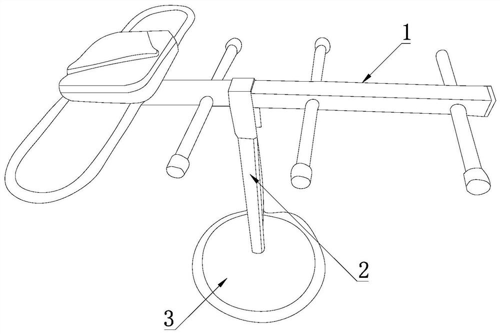

Image

  • Retractable structure beneficial to supporting antenna multi-scene wide application
  • Retractable structure beneficial to supporting antenna multi-scene wide application
  • Retractable structure beneficial to supporting antenna multi-scene wide application

Examples


Embodiment Construction

[0013] The following will clearly and completely describe the technical solutions in the embodiments of the present invention with reference to the accompanying drawings in the embodiments of the present invention. Obviously, the described embodiments are only some, not all, embodiments of the present invention. Based on the embodiments of the present invention, all other embodiments obtained by persons of ordinary skill in the art without making creative efforts belong to the protection scope of the present invention.

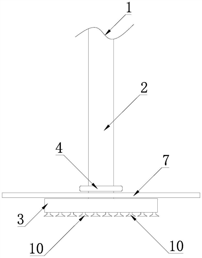
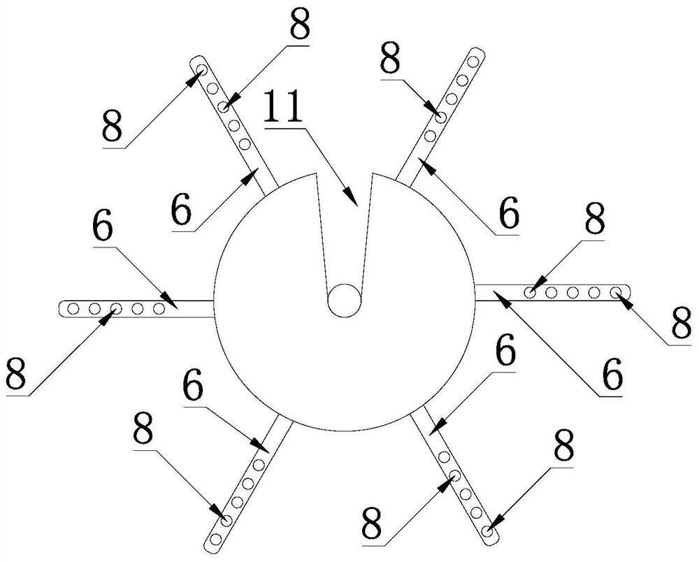
[0014] Please refer to the drawings in the description, the present invention provides a technical solution: a retractable structure that is conducive to the wide application of supporting antennas in multiple scenarios, including the antenna body 1, the connecting column 2 and the support plate 3, the support plate 3 includes the upper plate and the lower plate , the bottom end of the antenna body 1 is fixedly connected to the upper surface of the support plat...


PUM


Abstract

The invention discloses a retractable structure beneficial to supporting antenna multi-scene wide application, which comprises an antenna body, a connecting column and a supporting disc. The bottom end of the antenna body is fixedly connected with the upper disc surface of the supporting disc through the connecting column, rubber sucking discs are uniformly distributed on the lower disc surface of the supporting disc, and connecting belts are uniformly distributed on the annular outer surface side of a disc pressing ring. The connecting belt is fixedly connected with the pressure plate ring, the connecting belt comprises a first belt surface, rubber belt surface suckers are uniformly distributed on the first belt surface of the connecting belt, and the rubber belt surface suckers are fixedly connected with the connecting belt. On one hand, the use effect that the antenna body cannot be pressed and positioned more easily is achieved, on the other hand, multi-scene application is achieved, the multifunctional use effect is achieved, the situation that the mode which can be selected by a user for implementation is single is avoided, and more modes which can be selected for implementation are provided for the user.

Description

technical field [0001] The invention relates to a retractable structure that is conducive to the wide application of supporting antennas in multiple scenarios, and belongs to the technical field of antennas. Background technique [0002] The support structure of the antenna is a part of the antenna. For example, see the terrestrial wave digital antenna named Yongxing and the model DVB-T, including the antenna body, the connecting column and the support plate. The support plate includes the upper plate and the lower plate, and the bottom of the antenna body The end is fixedly connected to the upper surface of the support plate through the connecting column, rubber suction cups are evenly distributed on the lower surface of the support plate, and the antenna body is connected to the line. In the prior art, on the one hand, it cannot achieve the use of the antenna body that is easier to press and move. Effect, on the other hand, is not conducive to the realization of multi-scen...

Claims


Application Information

Patent Timeline
Patent Type & Authority Applications(China)
IPC IPC(8): H01Q1/12H01Q1/20
CPCH01Q1/125H01Q1/20
Inventor 杨慎谦沈勇杜玉雪
Owner 成都极乙通科技有限公司
Why Eureka
Eureka Blog
Learn More