Tooth yoke separation type permanent magnet synchronous motor stator structure

A permanent magnet synchronous motor and stator structure technology, applied in the field of electric motors, can solve problems such as shortening the service life of the motor, vibration and noise of the motor, and increased deflection of the motor, and achieve the effect of solving winding problems, high precision, and simple assembly

Pending Publication Date: 2021-08-31
湖州禾宇科技有限公司
View PDF0 Cites 0 Cited by
  • Summary
  • Abstract
  • Description
  • Claims
  • Application Information

AI Technical Summary

Problems solved by technology

However, due to the limitation of the diameter of the oil well pipe, it is still difficult to roll off the permanent magnet synchronous motor of the submersible screw pump, and it takes a long time. Although the block-type stator structure is convenient for winding, it is difficult to maintain a relatively high concentricity of the stator and rotor. Precision, for the slender structure motor, the eccentricity between the motor stator and rotor will generate a large unilateral magnetic pull, which will increase the deflection of the motor, causing vibration and noise of the motor, and shortening the service life of the motor

Method used


Image

  • Tooth yoke separation type permanent magnet synchronous motor stator structure
  • Tooth yoke separation type permanent magnet synchronous motor stator structure
  • Tooth yoke separation type permanent magnet synchronous motor stator structure

Examples


Embodiment Construction

[0019] The specific implementation manners of the present invention will be described in detail below in conjunction with the accompanying drawings. The described embodiments are only illustrations and explanations of the present invention, and do not constitute the only limitation of the present invention.

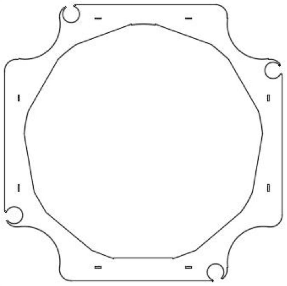
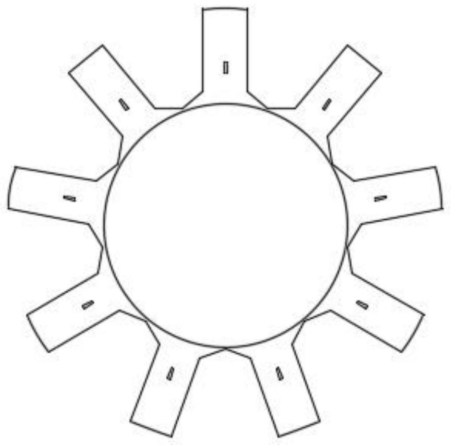
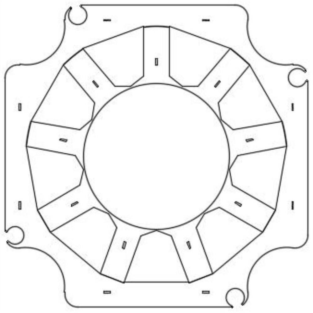
[0020] Such as Figure 1-Figure 6 As shown, the present invention includes a stator yoke and a stator tooth. The stator yoke and the stator tooth are punched and laminated by cold-rolled silicon steel sheets. The outside of the stator tooth is provided with a plurality of protrusions and surrounds the stator. For the stator teeth arranged in the tooth section, the inner hole profile of the stator yoke is formed by splicing multiple segments of arc lines, and the arc lines are connected by line segments, and each segment of arc line corresponds to a stator tooth on the stator tooth section. Preferably, stator slots are formed between the stator teeth, and insulating paper ...


PUM


Abstract

The invention discloses a tooth yoke separation type permanent magnet synchronous motor stator structure, which comprises a stator yoke part and a stator tooth part, the stator yoke part and the stator tooth part are formed by punching and laminating cold-rolled silicon steel sheets, and the outer side of the stator tooth part is provided with a plurality of convex stator teeth arranged around the stator tooth part. The inner hole outline of the stator yoke part is formed by splicing a plurality of sections of arc lines, the arc lines are connected through line segments, and each section of arc line corresponds to one stator tooth on the stator tooth part. The inner hole outline of the stator yoke part is formed by splicing the multiple sections of arc lines, the arc lines are connected through the line segments, and each section of arc line corresponds to the stator teeth on the stator tooth part, so that the problems that an existing spliced block stator structure is complex in splicing process and the roundness of a whole circle is difficult to guarantee are solved, and the problem of large internal winding difficulty due to small inner diameter of an integrated stator structure can be solved. The structure greatly solves the problem of winding, and is simple to assemble and high in precision.

Description

technical field [0001] The invention belongs to the technical field of electric motors, and in particular relates to a stator structure of a tooth-yoke separated permanent magnet synchronous motor. Background technique [0002] The submersible motor is not only the core part of the submersible screw pump oil production system, but also the subject of energy consumption. At present, the driving motors of submersible screw pumps at home and abroad are mostly asynchronous motors. However, the asynchronous motor of the submersible screw pump has disadvantages such as high production cost, high energy consumption, low efficiency, and short life under high temperature. The high speed makes it difficult to adapt to complex well conditions such as high-viscosity oil and high-sand content oil. Another development direction of the submersible screw pump drive motor is the permanent magnet synchronous motor of the submersible screw pump. Compared with the asynchronous motor of the su...

Claims


Application Information

Patent Timeline
Patent Type & Authority Applications(China)
IPC IPC(8): H02K1/14H02K1/18H02K3/34
CPCH02K1/146H02K1/185H02K3/345
Inventor 于涛刘勇霞
Owner 湖州禾宇科技有限公司
Why Eureka
Try Eureka