Engine input end shafting bearing testing machine and testing method

A bearing test and input-side technology, applied in mechanical bearing testing, aircraft component testing, etc., can solve the problems of high equipment input cost, low test efficiency, synchronous testing, etc., and achieve compact equipment structure, high test efficiency, and improved accuracy. Effect

Pending Publication Date: 2021-10-22
中浙高铁轴承有限公司
View PDF1 Cites 0 Cited by
  • Summary
  • Abstract
  • Description
  • Claims
  • Application Information

AI Technical Summary

Problems solved by technology

[0004] However, in this technical solution, the bearing at the input end of the engine cannot be tested synchronously, and different equipment needs to be tested, resulting in low test efficiency and high equipment investment costs.

Method used


Image

  • Engine input end shafting bearing testing machine and testing method
  • Engine input end shafting bearing testing machine and testing method
  • Engine input end shafting bearing testing machine and testing method

Examples


Embodiment 1

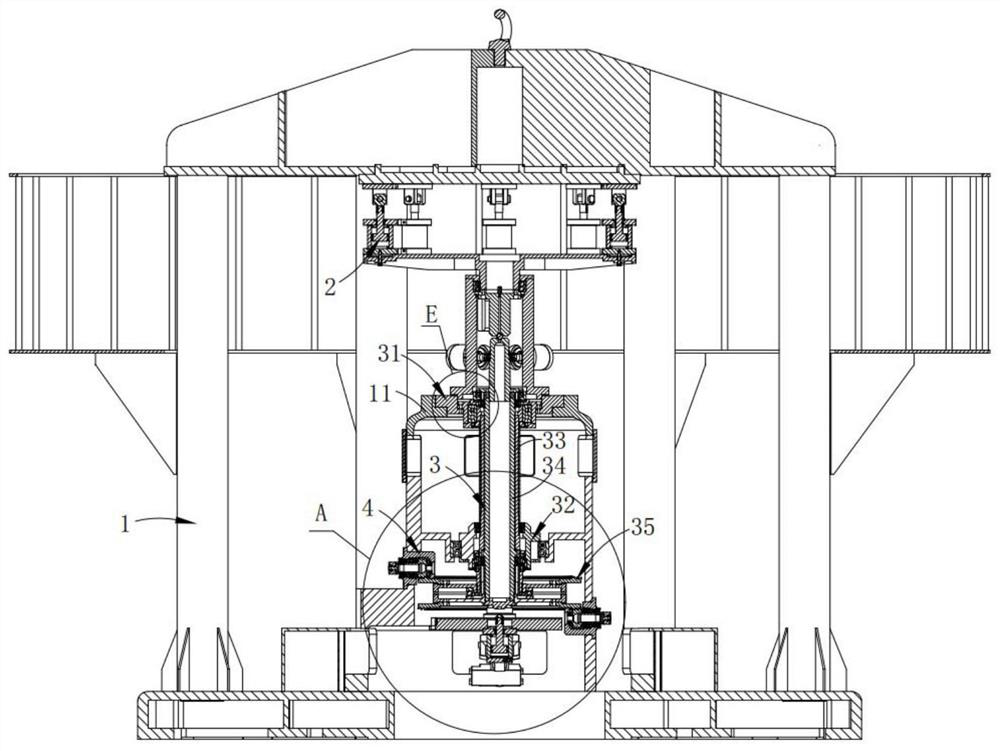
[0067] Such as Figure 1-2 As shown, a shaft bearing test machine at the input end of the engine includes:

[0068] A frame 1, the frame 1 is provided with a host casing 11;

[0069] Loading system 2, the loading system 2 is arranged below the top of the frame 1;

[0070] A dual-rotor system 3, the dual-rotor system 3 is arranged in the main engine housing 11 and connected to the output end of the loading force of the loading system 2; the dual-rotor system 3 includes a rotor power unit 35; and

[0071] Input-end bearing test system 4, the input-end bearing test system 4 is installed on the main engine housing 11 and connected with the rotor power unit 35 transmission; wherein, the input-end bearing test system 4 is provided with two groups, and respectively Be connected with the upper and lower ends of the rotor power unit 35;

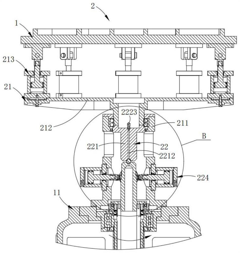
[0072] The loading system 2 includes:

[0073] A propeller simulation system 21, the upper end of the propeller simulation system 21 is connected...

Embodiment 2

[0101] Such as figure 1 , 5 , 7-10, wherein the same or corresponding components as those in the first embodiment use the corresponding reference numerals as in the first embodiment, for the sake of brevity, only the differences from the first embodiment are described below. The difference between this embodiment two and embodiment one is:

[0102] In this example, if figure 1 As shown, the dual-rotor system 3 includes:

[0103] An upper transition assembly 31, the upper transition assembly 31 is connected to the upper part of the main body casing 11;

[0104] a lower transition assembly 32, the lower transition assembly 32 is connected to the bottom of the main body housing 11;

[0105]Hollow outer rotor shaft 33, the upper end of the hollow outer rotor shaft 33 is connected to the connecting seat 313 of the upper transition assembly 31, the lower end of the hollow outer rotor shaft 33 and the lower transition assembly 32 pass through the first test bearing 101 is rotati...

Embodiment 3

[0135] Such as Figure 5-6 As shown, the components that are the same as or corresponding to those in the first embodiment are marked with the corresponding reference numerals in the first embodiment. For the sake of simplicity, only the differences from the first embodiment will be described below. The difference between this embodiment three and embodiment one is:

[0136] In this example, if Figure 5-6 As shown, the input end bearing testing system 4 includes:

[0137] An output bearing seat 41, the output bearing seat 41 is installed on the main engine casing 11 for installing the sixth test bearing 106; and

[0138] Transmission shaft 42, the transmission shaft 42 is connected with the inner ring of the sixth test bearing 106, one end of which is provided with a small bevel gear 421; the small bevel gear 421 is transmission connected with the rotor power unit 35.

[0139] Wherein, the bevel pinion gear 421 in one set of input end bearing test system 4 is in drive conn...


PUM


Abstract

The invention provides an engine input end shafting bearing testing machine, which comprises a loading system arranged below the top of a rack; a dual-rotor system which is connected with the output end of the loading force of the loading system; an input end bearing test system which is in transmission connection with the rotor power unit, the input end bearing test system comprises: an output bearing seat; and a transmission shaft; the double-rotor system is loaded through the loading system, the double-rotor system is driven to swing, then the rotor power unit is driven to swing, a transmission shaft in transmission connection with the rotor power unit is subjected to the vertical swing action of the rotor power unit, and a sixth test bearing is subjected to radial force and axial force and rotates at a high speed at the same time, the performance test of the sixth test bearing of the input end bearing is completed while the test of the to-be-tested bearing pack is completed, and the device is compact in structure, high in test precision and high in test efficiency.

Description

technical field [0001] The invention relates to the technical field of bearing testing, in particular to a testing machine and testing method for shafting bearings at the input end of an engine. Background technique [0002] Coaxial dual-rotor helicopter refers to the upper and lower rotors with one forward and one reverse rotation around the same theoretical axis. Due to the opposite steering, the torque generated by the two rotors is controlled in a flight with a constant heading. , which are mutually balanced in the state, and the unbalanced torque generated by the differential of the upper and lower rotor collective pitches can realize that the heading is a lifting surface and a vertical, horizontal and heading control surface. [0003] Chinese patent CN 105136459 B discloses a testing machine for combined joint bearings for a swing cylinder type helicopter tail rotor system. The servo-driven oil cylinder of the testing machine is fixed on the upper platform through the...

Claims


Application Information

Patent Timeline
Patent Type & Authority Applications(China)
IPC IPC(8): G01M13/04B64F5/60
CPCG01M13/04B64F5/60
Inventor 陈仁波张佩思陈文哲雷鸣浩单建明
Owner 中浙高铁轴承有限公司
Why Eureka
Try Eureka