
A kind of optical fiber mode field adapter assembly and preparation method thereof

A mode field adapter and optical fiber technology, applied in the field of all-fiber, can solve the problems of increasing the splice loss, difficult to achieve the mode field matching of the hollow core fiber, easy to damage the special cladding structure of the hollow core fiber, etc., so as to increase the cladding structure. Size, simple and efficient mode field matching, the effect of optimizing the fiber mode field profile

Active Publication Date: 2022-05-20
FUDAN UNIV
View PDF0 Cites 0 Cited by
  • Summary
  • Abstract
  • Description
  • Claims
  • Application Information

AI Technical Summary

Problems solved by technology

These methods have certain defects. For example, for adding a large mode field fiber as a transition fiber, more than two fusion splices will be introduced, resulting in a high total fusion splice loss; for using a graded-index fiber, it requires very precise fiber cutting length, length The slight deviation of the MF will lead to a rapid increase in the loss; the taper of the large mode field transition fiber will excite the high-order mode, increase the splice loss, and introduce multiple splice steps, which is not conducive to the preparation and low-loss coupling; the hollow-core fiber Tapering, for the special cladding structure that is easy to damage the hollow-core fiber; only using thermal expansion to increase the mode field of the single-mode fiber has limited effect, and it is also difficult to match the mode field with the hollow-core fiber, resulting in high splice loss

Method used


Image

  • A kind of optical fiber mode field adapter assembly and preparation method thereof
  • A kind of optical fiber mode field adapter assembly and preparation method thereof
  • A kind of optical fiber mode field adapter assembly and preparation method thereof

Examples


Embodiment

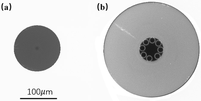
[0032] The selected solid core single-mode fiber 1 such as figure 2 As shown in (a), the core diameter is 8.2 μm, and the mode field diameter is 10.4 μm. The selected hollow core antiresonant fiber 3 such as figure 2 As shown in (b), the parameters are: the fiber core diameter is 35 μm, and the calculated mode field diameter is 25.2 μm. Since the cladding diameter of the single-mode fiber is much smaller than that of the hollow-core anti-resonant fiber, the splicing strength is low, and the mode field diameters of the two fibers are very different, resulting in a huge coupling loss. Considering the loss caused by mode-field mismatch, the coupling loss of the two fibers is estimated to be greater than 3dB.

[0033] In order to solve the problems of excessive splicing loss and low splicing strength of hollow-core anti-resonant optical fibers caused by mismatched mode fields and structural dimensions, an embodiment of the present invention provides an optical fiber mode field...


PUM

PropertyMeasurementUnit
diameteraaaaaaaaaa
diameteraaaaaaaaaa
diameteraaaaaaaaaa

Abstract

The invention belongs to the technical field of all optical fibers, in particular to an optical fiber mode field adapter assembly and a preparation method thereof. The optical fiber mode field adapter assembly of the present invention includes: a solid-core single-mode fiber with a first mode field diameter, a hollow-core anti-resonance fiber with a second mode field diameter, one end of the solid-core single-mode fiber is untreated, The other end has a reverse tapered tapered structure with a tapered transition, and the end face is coated with a high-temperature resistant anti-reflection film, which has a larger cladding diameter and mode field diameter than the untreated end of the solid-core single-mode fiber, and can be compared with The hollow-core optical fiber achieves cladding matching and mode-field matching coupling, and then one end of the reverse tapered structure is fused with the hollow-core optical fiber. The invention can simply and efficiently realize the mode field matching between the solid-core single-mode fiber and the hollow-core anti-resonance fiber, and solves the problem that the hollow-core fiber is incompatible with the solid-core fiber coupling in an optical fiber communication system.

Description

technical field [0001] The invention belongs to the technical field of all optical fibers, and in particular relates to an optical fiber mode field adapter assembly and a preparation method thereof. Background technique [0002] Hollow-core anti-resonant fiber is a new type of hollow-core fiber. In addition to the advantages of low nonlinearity and low loss transmission, it also has the advantages of simple fiber geometry, wider transmission window, and effective single-mode transmission. Therefore, this type of Optical fiber has attracted much attention in recent years. Hollow-core anti-resonant fiber has a high proportion of core energy, which provides an ideal platform for the interaction between light and matter. Hollow-core anti-resonant fiber is widely used in the fields of optical fiber sensing, optical fiber communication, nonlinear optics and high-energy laser transmission. It has very great application prospects, but in practical applications, it needs to be conne...

Claims


Application Information

Patent Timeline
Patent Type & Authority Patents(China)
IPC IPC(8): G02B6/255G02B6/25
CPCG02B6/2552G02B6/2551G02B6/2553G02B6/25
Inventor 肖力敏王草源
Owner FUDAN UNIV
Learn More