
Multifunctional nursing device for debridement in operating room
A nursing device and multi-functional technology, which is applied in the direction of surgery, nursing facilities, medical science, etc., can solve the problems of inability to adjust height, inability to adjust the position of debridement components, inconvenient use, etc.
- Summary
- Abstract
- Description
- Claims
- Application Information
AI Technical Summary
Problems solved by technology
Method used
Image

Examples
Embodiment 1
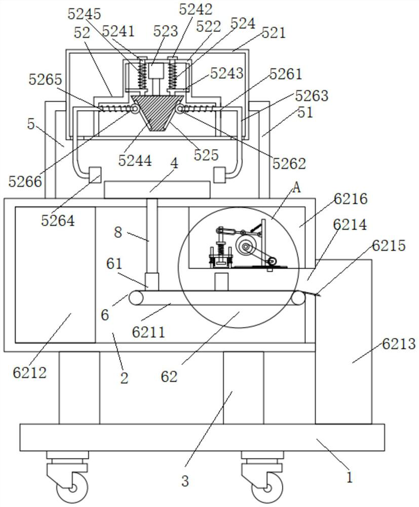
[0090] Embodiments of the present invention provide a multifunctional nursing device for debridement in an operating room, such as Figure 1-5 shown, including:
[0091] A movable base 1, the upper end of the movable base 1 is fixedly connected with a plurality of first lifting supports (which may be electric telescopic rods or hydraulic rods) 3;
[0092] The first box body 2 is fixedly connected to the upper end of the first lifting bracket 3;
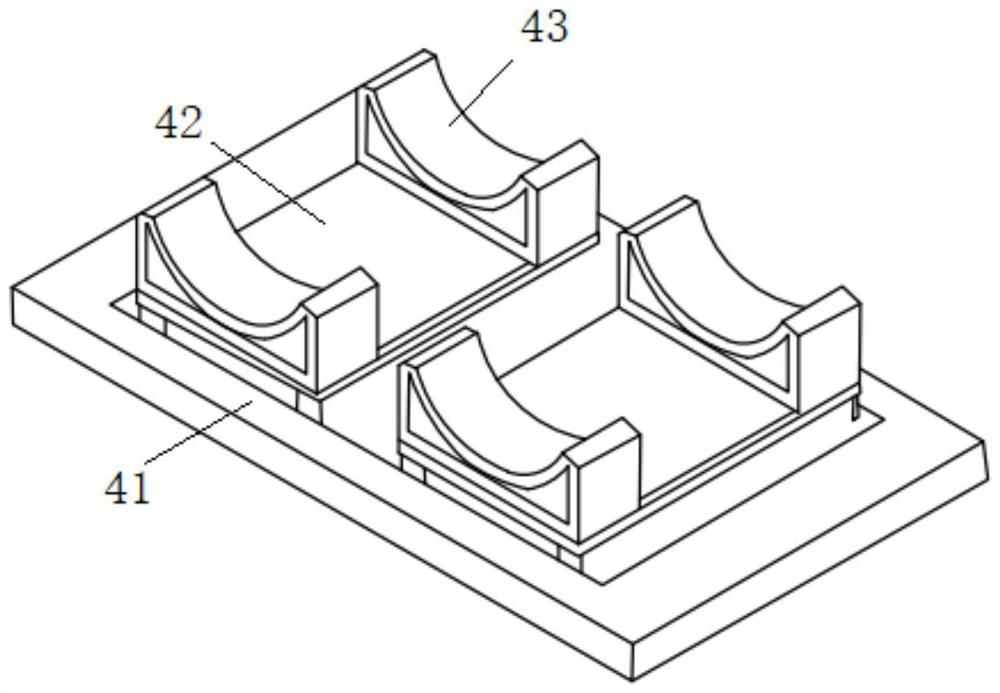
[0093] The placement seat 4 is installed on the upper end of the first box body 2;
[0094] The position-adjustable debridement component 5 is installed on the upper end of the first box body 2, and is used for debridement of the human body surface on the placement seat 4;
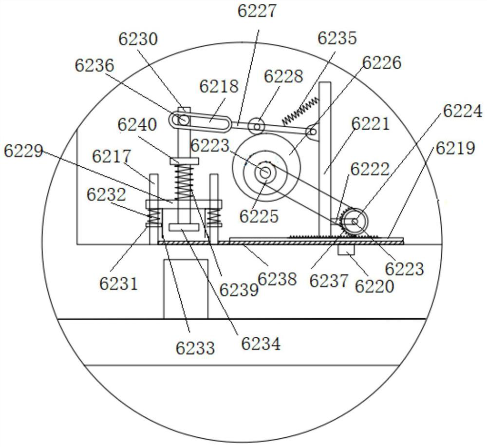
[0095] The collection assembly 6 is arranged in the first box body 2, a first inlet is arranged at the upper end of the first box body 2, and a first conduit 8 is arranged in the first inlet, and the first conduit 8 is used to communicate with all The liquid in...
Embodiment 2
[0101] On the basis of Example 1, such as figure 1 As shown, the position-adjustable debridement assembly 5 includes:
[0102] Two left-right symmetrical second connecting brackets 51 are fixedly connected to the upper end of the first box body 2 and are located on the left and right sides of the placement seat 4;
[0103] The position adjustment assembly 52 is connected with the second connecting bracket 51 , and the position adjustment assembly 52 is connected with a debridement device 5264 .
[0104] Preferably, the position adjustable component can be an existing manipulator.
[0105] The beneficial effect of the above technical solution is: the position adjustment assembly is installed through the second connecting bracket 51, and the position adjustment device is used to adjust the position of the debridement device.
Embodiment 3
[0107] On the basis of Example 2, such as figure 1 As shown, the position adjustment assembly 52 includes:
[0108] The second box body 521 is fixedly connected to the upper part between the two second connecting brackets 51;
[0109] The third box body 522 is fixedly connected inside the second box body 521;
[0110] The first electric telescopic rod 523 is vertically arranged, and the fixed end of the first electric telescopic rod 523 is fixedly connected to the inner wall of the upper end of the third box body 522, and the telescopic end of the first electric telescopic rod 523 is fixedly connected with an inverted trapezoidal block 5244;
[0111] Two first guide assemblies 524 are symmetrically connected to the upper end of the inverted trapezoidal block 5244 and are located on the left and right sides of the first electric telescopic rod 523. The first guide assemblies 524 include: a first vertical slide bar 5241, The upper part is slidingly connected with the upper en...
PUM
 Abstract
Description
Claims
Application Information