
Positioning ball shooting displacement device for football training
A football training and displacement device technology, applied to ball games, sports accessories, etc., can solve the problems of step-by-step, limited displacement effect, inconvenient replacement, etc., and achieve the effect of improving precision and accuracy, convenient operation and use, and improving the level
- Summary
- Abstract
- Description
- Claims
- Application Information
AI Technical Summary
Problems solved by technology
Method used
Image

Examples
Embodiment 1
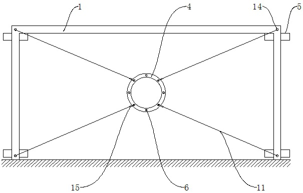
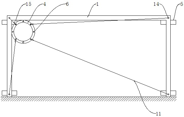
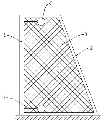
[0030] refer to Figure 1-6 , the present embodiment provides a positioning ball shooting displacement device for football training, comprising a door frame 1, an annular ball frame 4, a power box 5 and a controller 16, and the rear sides of both ends of the door frame 1 are provided with U-shaped net frames 2 , the U-shaped screen frame 2 opens toward the door frame 1, and the two ends of the U-shaped screen frame 2 are connected with the door frame 1; balls are connected between the U-shaped screen frames 2 at both ends of the door frame 1, and between the U-shaped screen frame 2 and the door frame 1 Net 3; the annular ball frame 4 is positioned at the front side of the door frame 1, and the annular ball frame 4 is uniformly provided with some first through holes 6, and the upper and lower ends of the U-shaped net frame 2 are provided with the power box 5, and the number of the power box 5 is four, They are respectively located on the rear side of the four corners of the doo...
Embodiment 2
[0033]Referring to the accompanying drawings, the present embodiment provides a positioning ball shooting displacement device for football training, including a door frame 1, an annular ball frame 4, a power box 5 and a controller 16, and the rear sides of the two ends of the door frame 1 are provided with U-shaped Screen frame 2, the opening of U-shaped screen frame 2 faces door frame 1, and the two ends of U-shaped screen frame 2 are connected with door frame 1; The ball net 3 is connected; the annular ball frame 4 is positioned at the front side of the door frame 1, and the annular ball frame 4 is uniformly provided with some first through holes 6, and the upper and lower ends of the U-shaped net frame 2 are provided with the power box 5, and the number of the power box 5 is Four, respectively located at the rear side of the four corners of the door frame 1; the power box 5 is provided with a housing 7, the two ends of the housing 7 are respectively provided with a motor 8 a...
PUM
 Abstract
Description
Claims
Application Information