Steel plate strip punching and deburring equipment

A technology for removing burrs and steel strips, which is applied in metal processing equipment, grinding/polishing equipment, cleaning methods and tools, etc. It can solve the problems that burrs cannot be removed cleanly, and the consistency of surface polishing cannot be guaranteed, so as to ensure uniformity , Guarantee the effect of quality

Inactive Publication Date: 2022-03-01
义乌市择木工业产品设计有限公司
View PDF2 Cites 3 Cited by
  • Summary
  • Abstract
  • Description
  • Claims
  • Application Information

AI Technical Summary

Problems solved by technology

However, this method does not control the grinding force, and cannot guarantee the consistency of the grinding degree of each surface
[0006] The Chinese patent with the application number CN201910782205.2 discloses a steel plate deburring device for power distribution cabinets. The first sandpaper is driven to rotate through the first helical gear and the first sandpaper installation head, and the second helical gear passes through the long teeth. The wheel drives the spur gear to rotate, and the spur gear drives the second sandpaper to rotate through the second sandpaper installation head, and the second elastic nut makes the circular driving sliding rod rotate 180 degrees, which solves the problem that the deburring equipment can only be cleaned on one side, and the burrs on the edge are Extruded to the other side, resulting in the problem that the burr cannot be removed cleanly, but the grinding effect on the surface of the workpiece is different with different grinding degrees. In order to ensure the uniformity of grinding, it is necessary to control the grinding degree

Method used


Image

  • Steel plate strip punching and deburring equipment
  • Steel plate strip punching and deburring equipment
  • Steel plate strip punching and deburring equipment

Examples


Embodiment 1

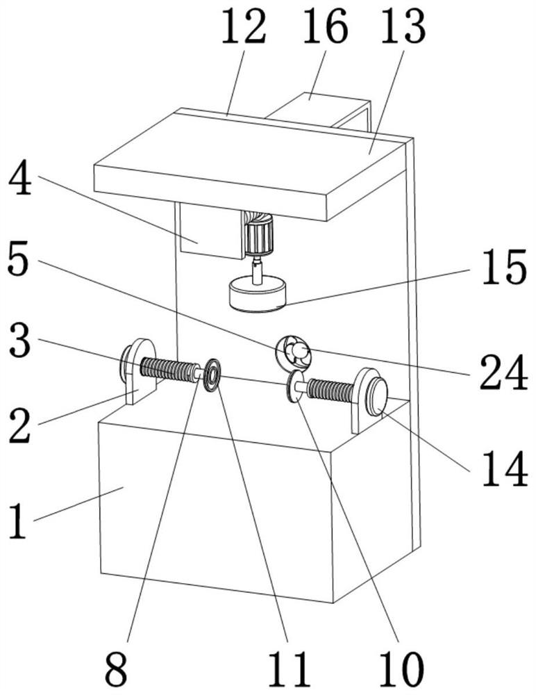
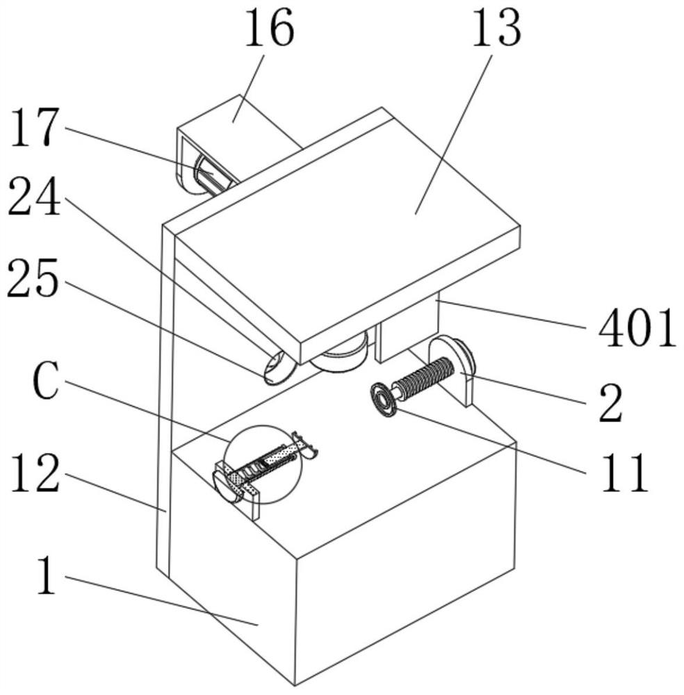
[0033] like Figure 1 to Figure 5 As shown, the present invention provides a steel strip punching and deburring equipment, including a mounting base 1, a mounting frame 2 is fixedly installed on the mounting base 1, a threaded rod 3 is movably socketed inside the mounting frame 2, and the threaded rod 3 is installed through the The frame 2 extends to the outside of the mounting frame 2 and is fixedly connected with a turntable 14. The inner cavity of the threaded rod 3 is fixedly connected with a return spring 6, and the other end of the return spring 6 is fixedly connected with a movable block 7, and the outer surface of the movable block 7 is connected to the screw thread. The side wall of the rod 3 inner cavity is movably connected, and the end of the movable block 7 away from the back-moving spring 6 is fixedly connected with a movable rod 8, which runs through the threaded rod 3 and is fixedly connected with the connecting block 10, and the other end of the connecting bloc...

Embodiment 2

[0046] During the working process of Example 1, the sides of the steel slats were polished, and the two sides of the steel slats were not ground. In order to realize the grinding of each side of the steel slats, the applicant, on the basis of Example 1, polished the The disc 15 is replaced by a clamp, and the rubber block 11 is replaced by a grinding brush.

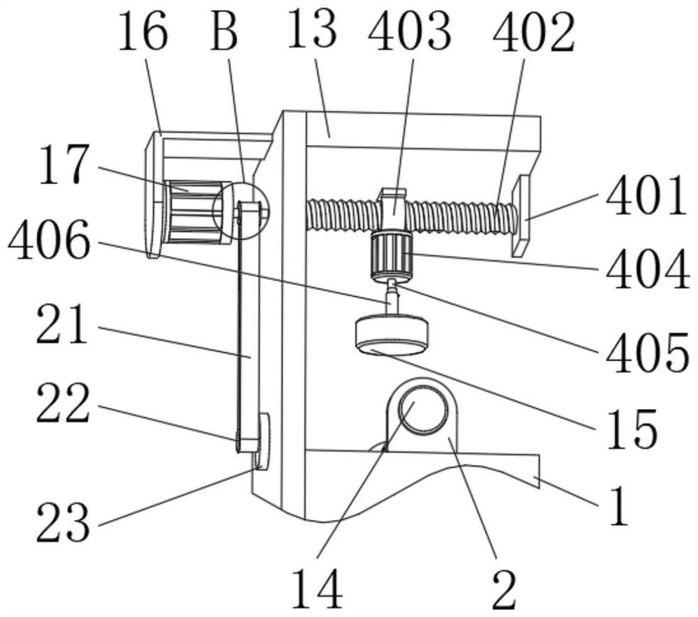
[0047] When in use, the steel strips are clamped by a clamp, the turntable 14 is rotated to drive the threaded rod 3 to rotate, and the threaded rod 3 is used to rotate to drive the movable block 7 to move, thereby adjusting the movable rod 8 to move to a suitable position, so that the grinding wool connected with the connecting block 10 The brush is in contact with the grinding surface of the steel strip, and the electric control telescopic rod 405 is controlled to expand and contract, so that the steel strip moves up and down. The steel strip is in contact with the grinding brush in the process of moving up and down, and...


PUM


Abstract

The invention belongs to the technical field of steel plate machining, and discloses a steel plate strip punching and deburring device which comprises a mounting base, a threaded rod is movably sleeved with a mounting frame, and the left end and the right end of the threaded rod are fixedly connected with a rotating disc and an anti-disengaging block correspondingly. According to the steel plate strip deburring device, a threaded rod and a movable rod are arranged, the threaded rod can be driven to rotate by rotating a rotating disc, a steel plate strip is extruded, and the steel plate strip is fixed, and deburring treatment can be conducted on the side face of the steel plate strip by starting a power motor; the pressure between the grinding disc and the steel plate strip is transmitted to the pressure sensor, the controller is used for controlling the elongation of the electric control telescopic rod, the contact pressure between the grinding disc and the steel plate strip is adjusted in real time to be always in a proper range, and the uniformity of the grinding effect on all the surfaces of the steel plate strip in the grinding process is guaranteed.

Description

technical field [0001] The invention belongs to the technical field of steel plate processing, in particular to a punching and deburring equipment for steel strips. Background technique [0002] Deburring is the removal of thorns or flashes formed at the intersection of parts and surfaces. Some burrs on mechanical parts are caused by plastic deformation during cutting, and some are flashes from casting, die forging, etc. Some are the residues of welding extrusion. With the improvement of industrialization and automation, in the field of mechanical processing, especially in the fields of aviation, aerospace, and instrumentation, the requirements for the precision of mechanical parts manufacturing and the miniaturization of mechanism design, the burr The harmfulness is particularly obvious, and it has gradually attracted people's attention, and began to study the formation mechanism and removal methods of burrs. [0003] At present, in the production and processing of steel s...

Claims


Application Information

Patent Timeline
Patent Type & Authority Applications(China)
IPC IPC(8): B24B9/04B24B41/06B24B41/00B08B5/02
CPCB24B9/04B24B41/06B24B41/00B08B5/02
Inventor 王传俊
Owner 义乌市择木工业产品设计有限公司
Why Eureka
Try Eureka