Polishing and cleaning device for mechanical part machining and working method of polishing and cleaning device

A technology for mechanical parts and cleaning devices, used in grinding drive devices, grinding/polishing safety devices, metal processing equipment, etc. Efficiency, convenient centralized collection and treatment, and the effect of reducing the degree of pollution

Active Publication Date: 2022-03-01
广德凯雷特机械科技有限公司
View PDF6 Cites 2 Cited by
  • Summary
  • Abstract
  • Description
  • Claims
  • Application Information

AI Technical Summary

Problems solved by technology

[0005] Aiming at the deficiencies in the prior art, the present invention provides a grinding and cleaning device for processing mechanical parts and its working method, which solves the problem of pollution to the environment caused by the sputtering of grinding waste in the existing grinding and cleaning device for processing and grinding of mechanical parts, and harms the operator. Issues that constitute a safety hazard

Method used


Image

  • Polishing and cleaning device for mechanical part machining and working method of polishing and cleaning device
  • Polishing and cleaning device for mechanical part machining and working method of polishing and cleaning device
  • Polishing and cleaning device for mechanical part machining and working method of polishing and cleaning device

Examples


Embodiment 1

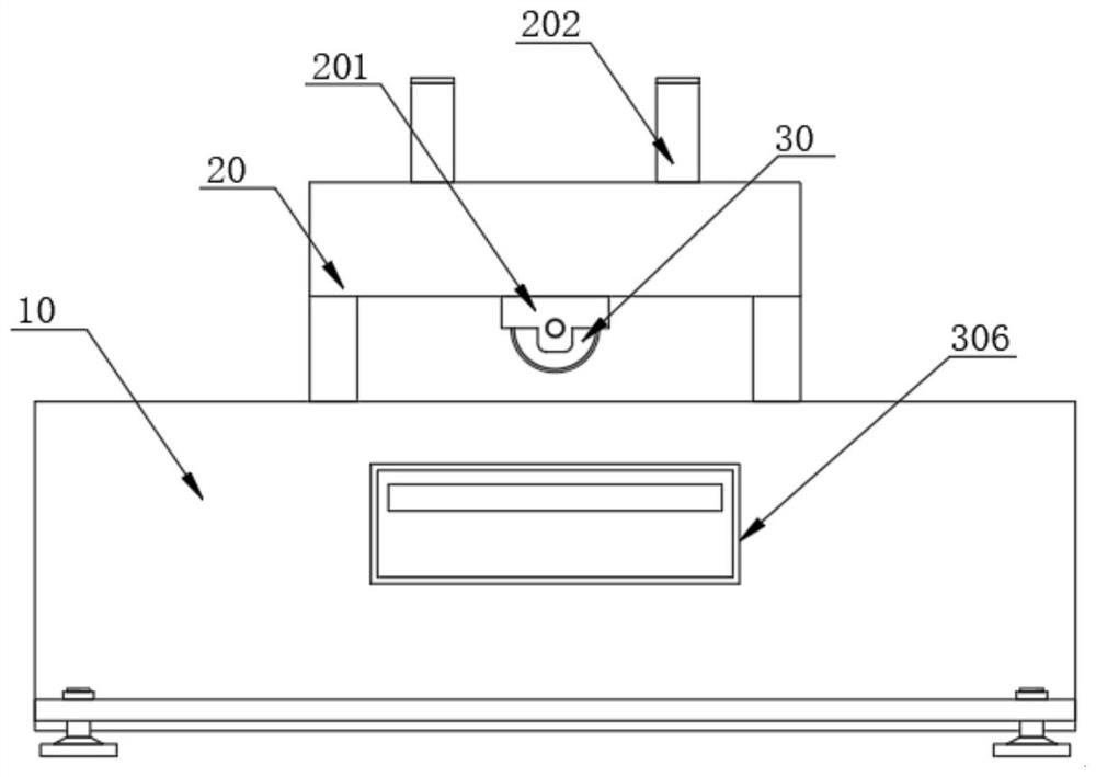
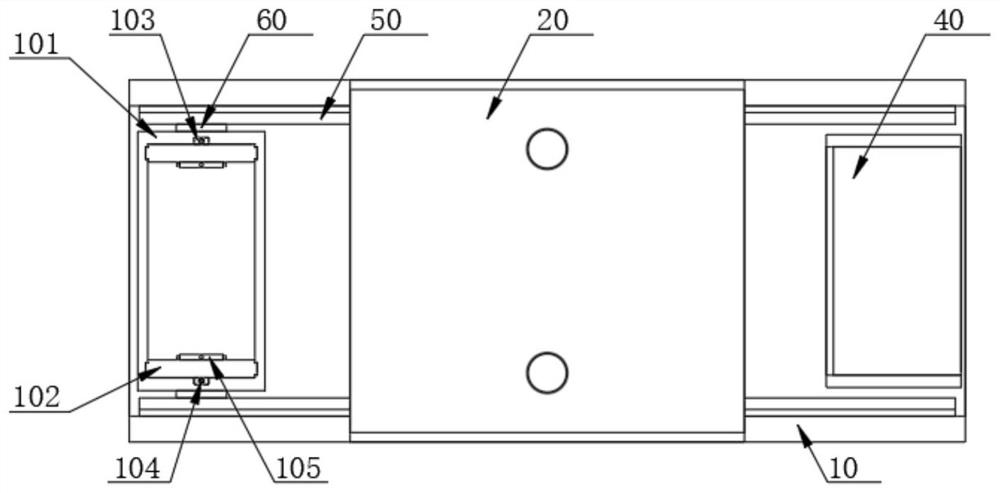
[0037] see Figure 1-8 As shown, a grinding and cleaning device for machining mechanical parts includes a frame 10 and an installation frame 20. The installation frame 20 is arranged on the top of the frame 10, and a grinding wheel 30 is arranged inside the installation frame 20. The top of the frame 10 is provided with a grinding wheel 30. The left side is provided with a fixing mechanism, and the right side of the top of the rack 10 is provided with a discharge rack 40, the front and rear of the inner wall of the rack 10 are provided with linear slide rails 50, and the opposite sides of the two linear slide rails 50 are slid A linear motor 60 is arranged, an adjustment mechanism is arranged above the inside of the mounting frame 20, and a recovery mechanism is arranged inside the frame 10 and located just below the installation frame 20;

[0038] The fixing mechanism includes a fixing frame 101, and the front and rear sides of the fixing frame 101 are respectively fixedly co...

Embodiment 2

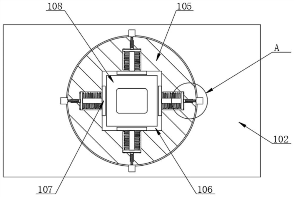
[0045] In the present invention, the telescopic assembly includes a movable rod 401, and one end of the movable rod 401 is fixedly connected to one side of the limit plate 107, the limit frame 105 is provided with a movable slot 402, and the inner of the movable slot 402 is slidably provided with a sliding plate 403 , one end of the movable rod 401 is fixedly connected with one side of the slide plate 403 , and the surface of the movable rod 401 is sleeved with a second spring 404 , a push rod 405 is slidably provided inside the limit frame 105 , and the inner screw connection of the push rod 405 There is a second screw 406, the peripheral surface of the limit frame 105 is provided with a second servo motor 407, and one end of the output shaft of the second servo motor 407 is fixedly connected with one end of the second screw 406 through a coupling;

[0046] Servo motor II 407 is used to drive the second screw 406 to rotate, and the second screw 406 makes one end of the push ro...

Embodiment 3

[0048] In the present invention, the inside of the movable frame 201 is also provided with air pumps 501, and two air pumps 501 are symmetrically arranged inside the installation frame 20, and both sides of the bottom of the movable frame 201 are provided with connecting grooves 502 which are matched with the connecting plate 303. And one end of the air outlets of the two air pumps 501 extends to the inside of the two connecting grooves 502 respectively. When the movable plate 301 is pushed up, the tops of the two connecting plates 303 are inserted into the inside of the two connecting grooves 502 respectively. When the parts are polished, air is blown into the air passages inside the two connecting plates 303 through the two air pumps 501, the air is blown on the surface of the mechanical parts, and the waste chips generated during the grinding process are blown into the blanking chute 305, It avoids the impact of grinding waste on grinding, and at the same time quickly collec...


PUM


Abstract

The invention relates to the technical field of machining, in particular to a polishing and cleaning device for mechanical part machining and a working method thereof.The polishing and cleaning device comprises a rack and a mounting frame, a fixing mechanism and a recycling mechanism are arranged in the rack, an adjusting mechanism is arranged in a fixing frame, and a polishing wheel is arranged in the fixing frame; in the process of polishing the mechanical part, two servo electric cylinders II push two movable plates to move upwards until connecting plates in the two movable plates are in contact with the bottom of a mounting frame, so that a closed cavity is formed between the mechanical part in the mounting frame and a polishing wheel; on one hand, it is guaranteed that waste chips generated in the grinding process cannot be scattered all around, it is guaranteed that metal waste chips cannot be sputtered in the grinding process, and a certain protection effect on operation safety of operators is achieved, on the other hand, the waste chips generated in the grinding process are conveniently collected and treated in a centralized mode, and the pollution degree of the grinding waste chips to the periphery of the device is reduced.

Description

technical field [0001] The invention relates to the technical field of mechanical processing, in particular to a grinding and cleaning device for processing mechanical parts and a working method thereof. Background technique [0002] Affected by various factors, the surface of mechanical parts is prone to rust after long-term use. In order to improve the working accuracy of mechanical parts and prolong their service life, it is necessary to derust the rusted mechanical parts. [0003] The invention patent with publication number CN111230683A proposes an integrated automatic grinding and derusting device for mechanical parts, including a bottom box, a sliding table is slidably installed on the upper part of the bottom box, and a sliding table is arranged inside the bottom box to control the sliding table along the upper part of the bottom box. A first drive mechanism for left and right reciprocating motion, a clamping assembly for fixing mechanical parts is installed on the u...

Claims


Application Information

Patent Timeline
Patent Type & Authority Applications(China)
IPC IPC(8): B24B27/033B24B41/00B24B41/06B24B55/06B24B55/12B24B47/12B24B47/04B24B41/02
CPCB24B27/033B24B41/005B24B41/06B24B55/06B24B55/12B24B47/12B24B47/04B24B41/02Y02P70/10
Inventor 卢永成许明甫刘国富
Owner 广德凯雷特机械科技有限公司
Why Eureka
Try Eureka