Rotary self-retaining wall pore-forming cast-in-place pile drill bit and drilling method

A cast-in-place pile and rotary technology, applied in drill bits, excavation, drilling equipment, etc., can solve the problems of sediment, high cost, slow impact pile progress, etc.

Pending Publication Date: 2022-07-08
湖南磐石机械有限公司
View PDF0 Cites 0 Cited by
  • Summary
  • Abstract
  • Description
  • Claims
  • Application Information

AI Technical Summary

Problems solved by technology

[0007] Advantages of rotary-dug hole-forming cast-in-place piles, using rotary-dug hole-forming steel casing retaining wall or mud retaining wall, which requires fewer operators, low labor intensity, fast progress in a single stratum, lower operating cost than artificial piles, and no downhole operation risk. Cheng There is no limit to the pile depth; the disadvantages are: rotary digging for complex strata requires more equipment for retaining walls, so the cost is high, and the bottom of the pile cannot be cleaned thoroughly, there is sediment, the quality of the hole is unstable, and the bearing capacity of a single pile with the same cross-section is higher than manual The piles are low and the waste of concrete in complex strata is large, and the cost is uncontrollable, sometimes even far exceeding that of artificial piles
[0008] Impact hole-forming piles, using impact holes, mud wall protection, adapt to complex strata, low labor intensity, but the progress of impact piles is very slow, the cost is high, the damage to the site is great, and the quality of piles is average

Method used


Image

  • Rotary self-retaining wall pore-forming cast-in-place pile drill bit and drilling method
  • Rotary self-retaining wall pore-forming cast-in-place pile drill bit and drilling method
  • Rotary self-retaining wall pore-forming cast-in-place pile drill bit and drilling method

Examples


Embodiment Construction

[0040] In order to make those skilled in the art better understand the technical solutions of the present invention, the present invention will be described in detail below with reference to the accompanying drawings. The description in this part is only exemplary and explanatory, and should not have any limiting effect on the protection scope of the present invention. .

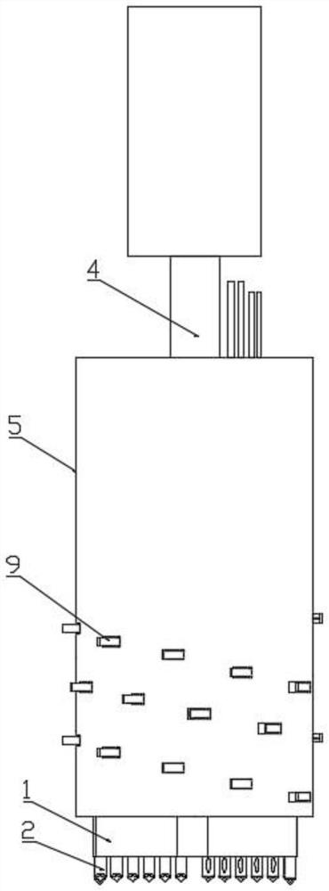
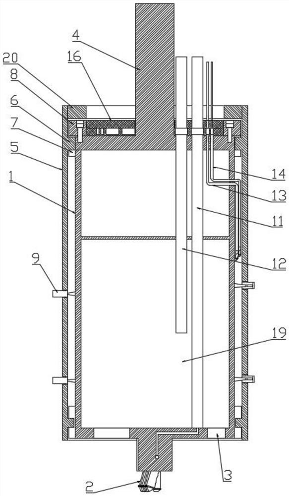
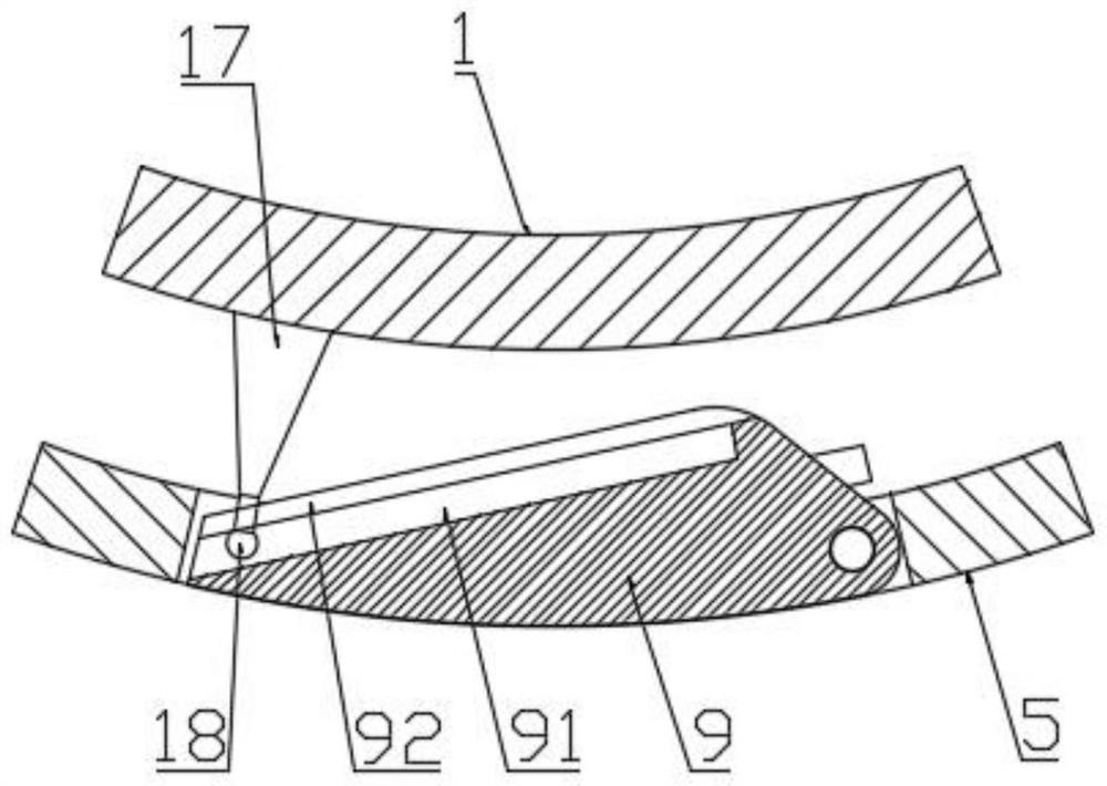
[0041] see Figure 1 to Figure 7 , in a specific embodiment, a rotary self-protecting wall hole-forming cast-in-place pile drill bit includes a main drill part 1, the lower end of the main drill part 1 is provided with a drill bit 2, and the outer wall of the main drill part 1 is sleeved with a rotatable The outer wall of the protection wall 5; the inner wall of the outer wall of the protection wall 5 is provided with a convex part 6; the outer wall of the main drill part 1 is provided with a groove 7 for clipping into the convex part 6 to limit the rotation range of the outer wall of the protection wall 5; ...


PUM


Abstract

The invention relates to the technical field of constructional engineering, in particular to a rotary self-retaining wall pore-forming cast-in-place pile drill bit and a drilling method. A rotary self-retaining wall hole-forming cast-in-place pile drill bit comprises a main drill part, a drill bit body is arranged at the lower end of the main drill part, and the outer wall of the main drill part is sleeved with a rotatable retaining wall outer barrel; a convex part is arranged on the inner wall of the protective wall outer cylinder; the outer wall of the main drill part is provided with a groove used for being clamped into the protruding part to limit the rotation range of the protection wall outer cylinder. Notches are distributed in the protective wall outer cylinder, and blades capable of turning over transversely are arranged in the notches; the main drill part is provided with a pushing piece used for controlling the blades to be opened and closed. Grout outlet holes for outputting concrete grout and liquid outlet holes for outputting an accelerator are formed in the blades; a mud inlet hole is formed in the lower end of the main drill part, and a mud suction pipe is arranged in the main drill part and communicated with the mud inlet hole. According to the invention, the self-protection wall of the cement-mixed soil can be realized, and the cement-mixed soil protection wall can be rapidly formed by injecting cement paste and an accelerator into the protection wall layer during hole forming.

Description

technical field [0001] The invention relates to the technical field of construction engineering, in particular to a rotary self-protecting wall hole-forming cast-in-place pile drill bit and a drilling method. Background technique [0002] The cast-in-place pile system refers to the pile holes formed in the foundation soil by means of mechanical drilling, steel pipe excavation or manual excavation at the project site, and the piles made of steel cages and poured concrete are placed in them. , Cast-in-place piles can be divided into immersed pipe cast-in-place piles, bored cast-in-place piles and dig-hole cast-in-place piles. [0003] There are two types of existing hole-forming cast-in-place piles: artificial hole-forming and mechanical hole-forming: [0004] 1. The artificial hole-forming pile adopts manual excavation and reinforced concrete wall, which requires less equipment, and can be poured at one time after the hole is completed in a large area, reducing the on-site c...

Claims


Application Information

Patent Timeline
Patent Type & Authority Applications(China)
IPC IPC(8): E21B10/44E21B10/26E21B33/13E02D17/08E02D15/04
CPCE21B10/44E21B10/26E21B33/13E02D17/08E02D15/04
Inventor 曾永立
Owner 湖南磐石机械有限公司
Why Eureka
Try Eureka