Data communication terminal appliance and method of changing data communication rate using such appliance

A technology of data communication and terminal equipment, which is applied in the field of data communication terminal equipment to achieve the effect of avoiding the narrowing of the downlink communication area

Inactive Publication Date: 2005-09-21
NEC CORP
View PDF0 Cites 0 Cited by
  • Summary
  • Abstract
  • Description
  • Claims
  • Application Information

AI Technical Summary

Problems solved by technology

[0015] The present invention has solved the problems that arise in the spread spectrum mobile communication system

Method used


Image

  • Data communication terminal appliance and method of changing data communication rate using such appliance
  • Data communication terminal appliance and method of changing data communication rate using such appliance
  • Data communication terminal appliance and method of changing data communication rate using such appliance

Examples


Embodiment Construction

[0034] The data communication terminal equipment of the preferred embodiment and the method for changing the data communication rate using the data communication terminal equipment according to the present invention will be described in detail below with reference to the accompanying drawings. In the following description, many specific technical features are proposed for the public to understand the present invention, but it is obvious to those of ordinary skill in the art that the present invention can be implemented without using these specific features.

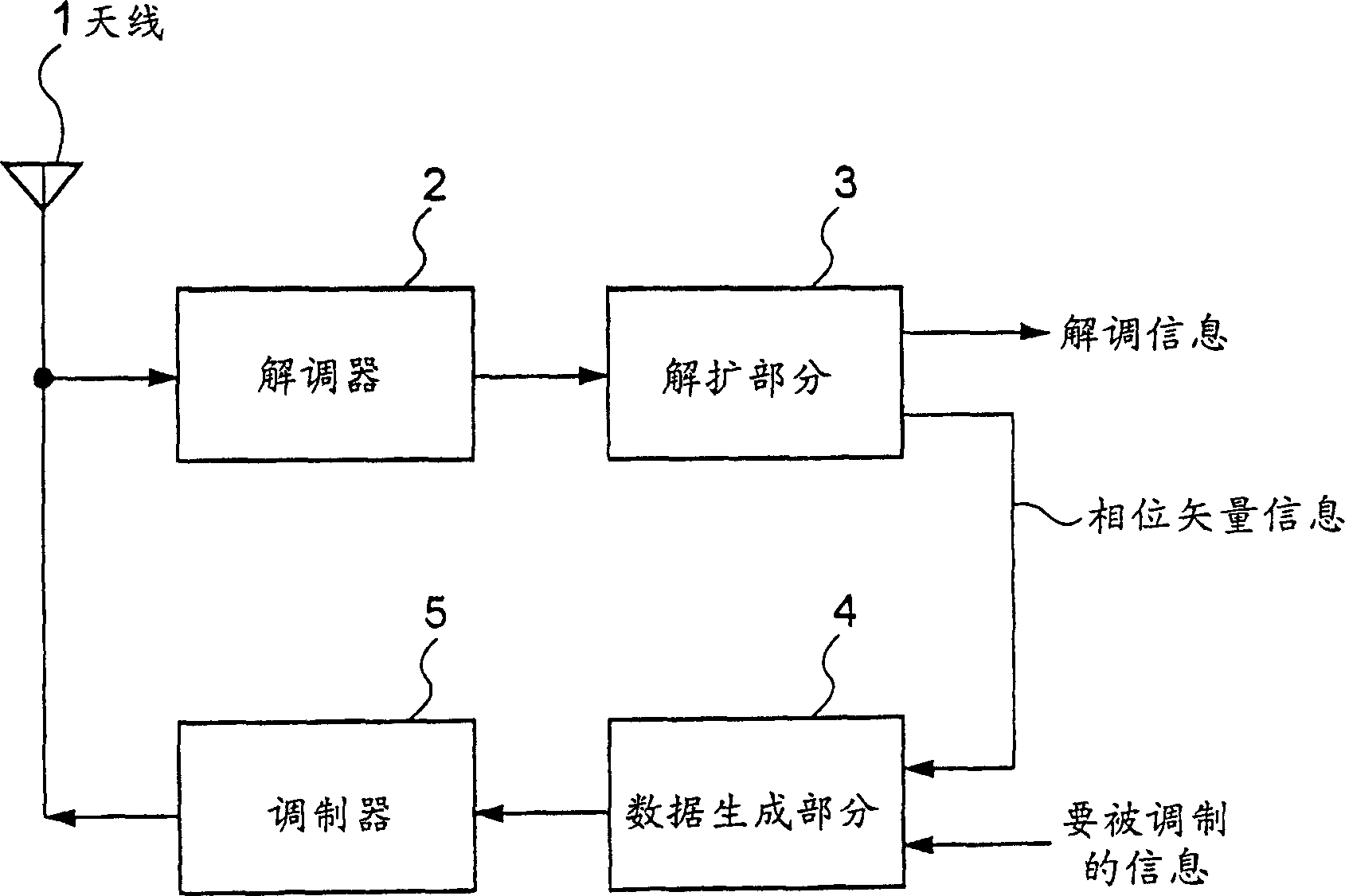
[0035] figure 1 A structure of a data communication terminal device according to an embodiment of the present invention is shown. exist figure 1 Among them, the data communication terminal equipment of the present invention includes an antenna 1, a demodulator 2 for receiving a downlink signal from a radio base station equipment (not shown), a downlink signal for despreading (despread) CDMA (Code Division Multiple Acc...


PUM


Abstract

A data communication terminal device does not narrow a downlink communication area upon transition from stopping state to moving state and can prevent call interruption of other terminal device. The data communication terminal device to be used in a spread spectrum mobile communication system monitors variation of moving condition of the device, and demands change of a data communication rate to a radio base station equipment depending upon a result of monitoring.

Description

technical field [0001] The invention relates to a data communication terminal device and a data communication rate changing method using the communication terminal device. More specifically, the present invention relates to a data communication terminal equipment used in a spread spectrum mobile communication system. Background technique [0002] The state of the data communication terminal equipment in the spread spectrum mobile communication system is usually divided into a static state and a moving state. Furthermore, the data rate on the downlink that the data communication terminal equipment receives from the radio base station equipment can be high and low. The downlink transmission power of the radio base station apparatus described above will be discussed below with reference to FIGS. 5 and 6. FIG. [0003] Figure 5 shows the situation where the data communication terminal equipment is in a static state. In FIG. 5, "A" indicates a state where communication is perf...

Claims


Application Information

Patent Timeline
Patent Type & Authority Patents(China)
IPC IPC(8): H04J13/00H04B1/707H04L1/00H04M1/725H04M11/00H04W28/00H04W28/18H04W76/02H04W88/02
CPCH04L1/0025Y02B60/31H04L1/0002Y02D30/50H04B7/26
Inventor 松木彻
Owner NEC CORP
Why Eureka
Try Eureka