Method for eliminating image rotation caused by 45 degree scanning lens

A technology of scanning mirrors and image square coordinates, which is applied in graphics and image conversion, image data processing, complex mathematical operations, etc., can solve the problems of reducing the reliability of instruments, increasing the degree of polarization of instruments, and the long optical path of remote sensing instruments, etc. cost, reducing polarization responsivity, and improving detection sensitivity

Inactive Publication Date: 2003-06-25
SHANGHAI INST OF TECHNICAL PHYSICS - CHINESE ACAD OF SCI
View PDF0 Cites 12 Cited by
  • Summary
  • Abstract
  • Description
  • Claims
  • Application Information

AI Technical Summary

Problems solved by technology

However, the K-mirror eliminates image rotation and has a relatively large disadvantage: the optical path of the remote sensing instrument is relatively long, and there is one more moving part in the optical path, which may reduce th

Method used


Image

  • Method for eliminating image rotation caused by 45 degree scanning lens
  • Method for eliminating image rotation caused by 45 degree scanning lens
  • Method for eliminating image rotation caused by 45 degree scanning lens

Examples


Embodiment Construction

[0067] based on the following figure 1 and figure 2 , to illustrate the preferred embodiment of the present invention.

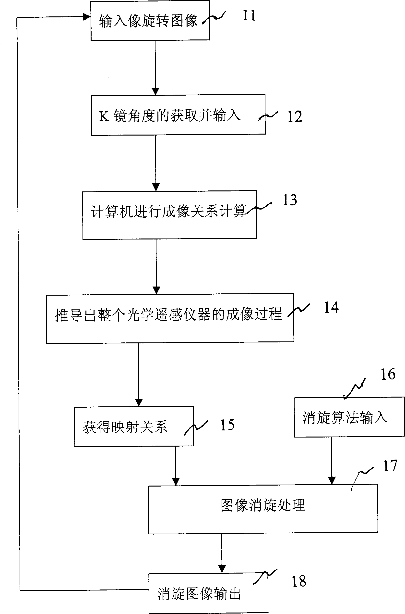
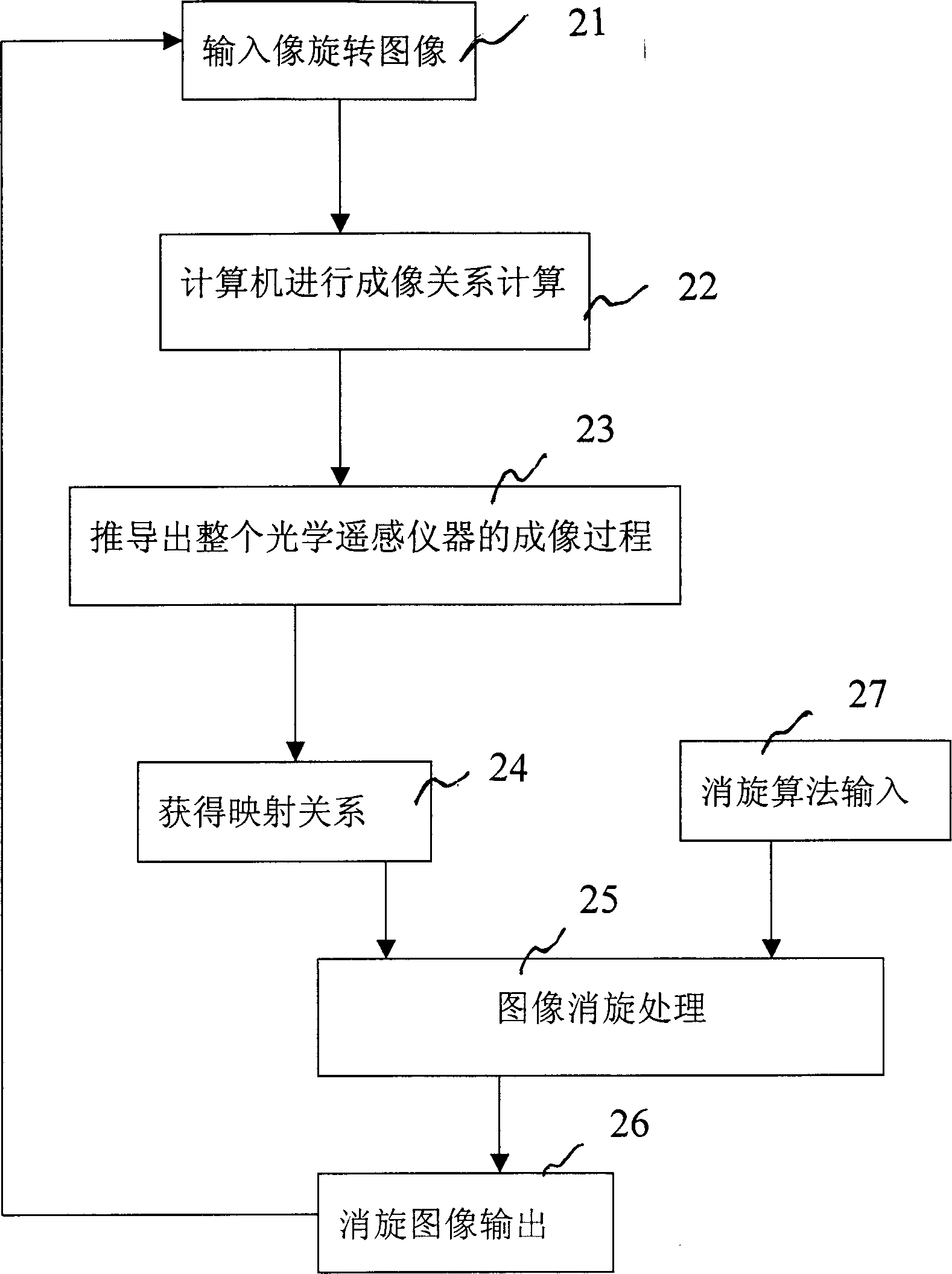
[0068] Such as figure 1 Shown, when the present invention is due to the derotation processing when the K mirror breaks down, at first, to the input image data (step 11) of image rotation by the mode of downlinking to computer, then, K mirror angle acquisition and input in this computer ( Step 12), the computer calculates the imaging relationship (step 13), derives the imaging process of the entire optical remote sensing instrument from the most basic reflection law (step 14), and obtains the mapping relationship between the image coordinates of the image rotation and the derotation image coordinates ( Step 15), use the coordinate mapping relationship and input the derotation algorithm (step 16) to derotate the entire image (step 16), and finally output the derotation image (step 17), using the above derotation image as input, Go back to step 11 and execu...


PUM


Abstract

The method of eliminating image rotation caused by 45 deg scanning lens is suitable for eliminating image rotatino in case of faulted K lens and no K lens. The method includes at least the folloiwng steps: rotating computer input image; calculating imaging relationship in computer; deducing the imaging process of the optical instrument from the basic reflection law; obtaining the mapping relationship between the image rotating coordinate and rotation elimianting image coordinate; eliminating rotation of the whole image frame; and output rotation eliminated image; circular execution. For faulted K lens, there include also the steps of obtaining K lens angle and inputting to computer. The present invention can eliminate rotation of image, simplify optical path of remote sensing instrument, raise the reliability of instrument in satellite.

Description

technical field [0001] The invention relates to a method for eliminating the image rotation caused by a 45-degree scanning mirror, in particular to a method for eliminating the image rotation caused by an optical remote sensing instrument using a 45-degree rotating scanning mirror in the parallel scanning process of a multi-element detector. method of rotation. Background technique [0002] The development and use of optical remote sensing instruments is to realize the quantitative application of remote sensing data, and the premise of quantitative application is the high radiometric calibration accuracy that the instrument itself must have. According to the long-term on-orbit observation of various optical remote sensing instruments, it is found that the on-orbit performance of remote sensing instruments is gradually attenuated, and this attenuation is inevitable. In the short-wave region near the ultraviolet, this attenuation can even be as high as 25%. In this case, if ...

Claims


Application Information

Patent Timeline
IPC IPC(8): G02B26/10G06F17/10G06T3/60
Inventor 黄小仙孙德新冯旗张锷
Owner SHANGHAI INST OF TECHNICAL PHYSICS - CHINESE ACAD OF SCI
Why Eureka
Try Eureka