Imaging device of correcting longitudinal alignment, and its correction method

An imaging device and a corresponding technology, which are applied to the equipment of the electric recording process applying the charge pattern, the electric recording process applying the electric charge pattern, the pile separation, etc., can solve the problem that the feed error is not accurately corrected, and the printed page goes too far. And other issues

Inactive Publication Date: 2003-12-24
SAMSUNG ELECTRONICS CO LTD
View PDF1 Cites 7 Cited by
  • Summary
  • Abstract
  • Description
  • Claims
  • Application Information

AI Technical Summary

Problems solved by technology

And, the printing position part of the printed page is divided into a first part where the printed page is inserted into the pickup roller and the feed roller, a second part where the printed page is inserted into the pickup roller, the feed roller and the exit roller, and a printed page is inserted into the feed roller and the exit roller. The third section in the roller, and the fourth section where the printed page is inserted into the exit roller, and, at the moment the printed page is inserted into each section, there is a phenomenon that causes the printed page to go over the top
[0014] Then, for the feed error value that appears different depending on the print mode, print page, and print position section, the feed error value was corrected all at once using a predetermined correction value in the past, so that the feed error value could not be accurately corrected.

Method used


Image

  • Imaging device of correcting longitudinal alignment, and its correction method
  • Imaging device of correcting longitudinal alignment, and its correction method
  • Imaging device of correcting longitudinal alignment, and its correction method

Examples


Embodiment Construction

[0029] Preferred embodiments of the invention, examples of which are shown in the accompanying drawings, will now be described in detail, wherein like reference numerals refer to like parts throughout. The embodiments are described in order to explain the present invention by referring to the figures.

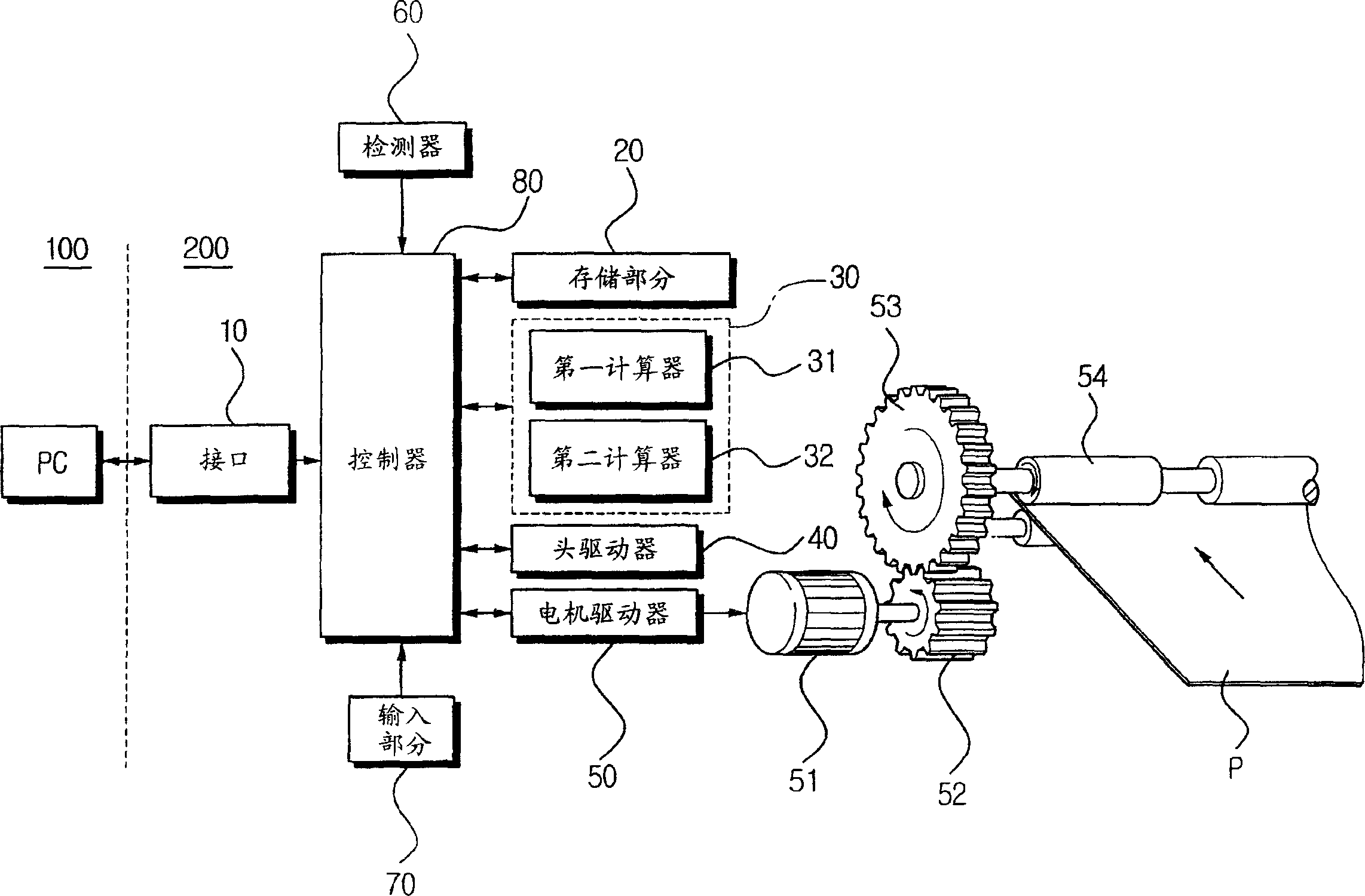
[0030] In general, image forming devices such as printers are classified into C-type path (front input / front output), box-type (bin) path (rear input / front output) and Single Sheet Input (SSI) or manual path, and according to an embodiment of the present invention, in figure 1 and 4 An inkjet printer 200 with a C-path is described in .

[0031] like figure 1 As shown, the inkjet printer 200 includes an interface 10, a storage section 20, a calculator 30, a head driver 40, a motor driver 50, a detector 60, an input section 70, a controller 80, and the like.

[0032] The interface 10 receives print data and a print command from a computer (PC) 100 , and stores the received pr...


PUM


Abstract

An image forming device has a first calculator applying any one of setting values for plural alignment patterns pre-set corresponding to magnitudes of feeding error values according to feeding amounts of a printing sheet of paper by feeding rollers and calculating first correction values for the feeding error values depending upon operation modes, a second calculator calculating second correction values for the feeding error values depending upon the printing sheet, and a controller controlling the feeding rollers to be driven to correct the feeding error values depending upon the operation modes and the printing sheet using the first and second correction values calculated by the first and second calculators. Accordingly, the image forming device can correct the feeding error values depending upon the operation modes, the printing sheet, and the printing position sections, thereby obtaining a best quality images in the respective modes.

Description

[0001] Cross Reference Related Applications [0002] This application claims priority from Korean Patent Application No. 2002-30690 filed with the Korean Intellectual Property Office on May 31, 2002, which is hereby incorporated by reference. technical field [0003] The present invention relates to an imaging device, in particular to an imaging device capable of correcting longitudinal alignment, and a correction method thereof. Background technique [0004] Generally speaking, an image forming apparatus such as a photocopier, a scanner, a printer, etc. picks up a sheet of printing paper one by one from a paper supply cassette, transfers the printing sheet through a predetermined conveying path, and moves the printing sheet to a driving feeding roller (feeding roller). roller) to feed the feeding position of the printed page. The feeding roller driven by the controller according to the printing command conveys the printing page at the feeding position at an appropriate tim...

Claims


Application Information

Patent Timeline
Patent Type & Authority Applications(China)
IPC IPC(8): B41J2/01B41J13/02B41J29/393B65H5/06G03G15/00
CPCB41J29/393G03G15/00
Inventor 李龙德朴炫基
Owner SAMSUNG ELECTRONICS CO LTD
Why Eureka
Try Eureka