Distributed monitoring method based on bidirectional information flow

A distributed monitoring and information flow technology, applied in the information field, can solve problems such as one-way information flow, cost of manpower, material and financial resources, and difficulty in satisfying complex control.

A distributed monitoring and information flow technology, applied in the information field, can solve problems such as one-way information flow, cost of manpower, material and financial resources, and difficulty in satisfying complex control.

CN1485737AInactive Publication Date: 2004-03-31TIANJIN ZHONGKE BLUEWHALE INFORMATION TECH +1

Image

  • Distributed monitoring method based on bidirectional information flow
  • Distributed monitoring method based on bidirectional information flow
  • Distributed monitoring method based on bidirectional information flow

Examples


Embodiment Construction

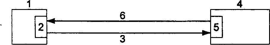
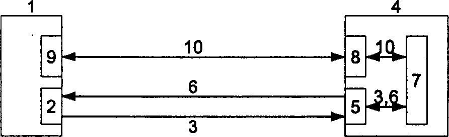
[0012] figure 2 It is a schematic structural diagram of a distributed monitoring system based on two-way information flow. and figure 1 Compared with the structure of the traditional distributed monitoring system shown, the difference is that after the monitoring, display and alarm 5 on the monitoring side 4 receive the monitoring information 3, it will be sent to the central analysis and control 7, and the central control and analysis 7 pair Analyze and make decisions on the received monitoring information 3, transmit file data or control command data 10 to the monitored party 1 through the control information channel interface 8 on it and the control information channel interface 9 on the monitored party 1, and control the monitored party 1 Execute the desired handler or control command.

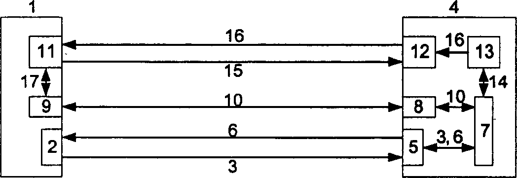
[0013] Using a distributed monitoring system based on two-way information flow, when the analysis and control software of the monitoring party finds that the monitored party has a fault...


PUM


Abstract

The invention discloses a distributed monitor and control method based on bi-directional information flow which comprises, receiving the monitoring information, receiving the monitoring information and proceeding analysis and decision-making, receiving the accepting file data and control command data, when the monitoring party finds the accident or potential fault on the monitored party, the corresponding processing scheme can be determined according to the different fault and clearing the fault.

Description

technical field [0001] The invention relates to the field of information technology, in particular to a distributed monitoring method based on bidirectional information flow. Background technique [0002] With the rapid development of network technology, various distributed application systems based on network interconnection are gradually increasing. Such as Web server clusters that provide WWW services, database server clusters that provide database services, computing server clusters that provide computing services, etc. In many applications, such as data centers, e-commerce, scientific computing, etc., the cluster contains a large number of server nodes and network devices, often ranging from dozens to hundreds, and the number of these server nodes and devices The distribution of physical locations may also be very wide. How to effectively monitor and control the above-mentioned distributed system, so as to detect and eliminate the existing and potential faults in the ...

Claims


Application Information

Patent Timeline
31 Mar 2004
Publication
CN1485737A
IPC
G06F9/38; G06F11/30
Inventors
范中磊; 许鲁