Shift control apparatus and shift control method for a vehicular automatic transmission

A technology of automatic transmission and shift control, applied in the control device, engine control, transmission control and other directions, can solve problems such as shift shock, and achieve the effect of eliminating shift shock

Inactive Publication Date: 2004-06-16
TOYOTA JIDOSHA KK
View PDF0 Cites 4 Cited by
  • Summary
  • Abstract
  • Description
  • Claims
  • Application Information

AI Technical Summary

Problems solved by technology

But doing so can cause shift shock with little or no drop in engine speed

Method used


Image

  • Shift control apparatus and shift control method for a vehicular automatic transmission
  • Shift control apparatus and shift control method for a vehicular automatic transmission
  • Shift control apparatus and shift control method for a vehicular automatic transmission

Examples


Embodiment Construction

[0034] In the following description and in the drawings, the invention is described in detail with reference to exemplary embodiments.

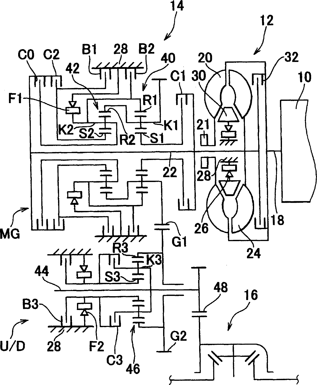
[0035] FIG. 1 is a schematic diagram of a transverse vehicle drive device of a vehicle such as a FF (Front Engine Front Drive) vehicle. One is an internal combustion engine such as a gasoline engine, and the output of the engine 10 is transmitted to the drive wheels (front wheels) through a power transmission device such as a torque converter 12, an automatic transmission 14 and a differential gear device (differential) 16. The torque converter 12 includes a pump wheel 20 connected to the crankshaft 18 of the engine 10, a turbine 24 connected to the input shaft 22 of the automatic transmission 14, and fixed on a housing 28 as a non-rotating member via a one-way clutch 26. The stator 30 and the lock-up clutch 32 directly connect the crankshaft 18 and the input shaft 22 via a buffer (not shown). A mechanical oil pump 21 such as a gear pump is ...


PUM


Abstract

A shift control apparatus for a vehicular automatic transmission provided with a fuel cut apparatus which cuts off fuel supplied to an engine when an engine speed exceeds a predetermined value during deceleration of a vehicle, and an automatic transmission in which a gearshift is achieved with a clutch-to-clutch downshift in which a hydraulic friction device to be released is released and a hydraulic friction device to be applied is applied, further includes a controller. The controller corrects, through learning control, an apply pressure of at least one of the hydraulic friction devices to be operated for the clutch-to-clutch downshift such that an amount of drop in a rotational speed of an input shaft of the automatic transmission increases when that amount of drop is less than a predetermined value during the clutch-to-clutch downshift.

Description

technical field [0001] The present invention relates to a shifting (shifting) control device and shifting control of a vehicle automatic transmission capable of suppressing a decrease in the rotational speed of an input shaft during a clutch-to-clutch downshift when the vehicle is decelerating method. Background technique [0002] A known shift control device for an automatic transmission for a vehicle is that it performs shift hydraulic control during a clutch-to-clutch downshift to reduce a disengagement-side hydraulic friction engagement engaged for a predetermined rotational speed before shifting The engagement pressure of the device is simultaneously increased to realize the engagement pressure of the hydraulic friction engagement device on the engagement side at a predetermined speed after shifting. For example, according to JP(A) 11-287318, in the clutch-to-clutch downshift, the engagement pressure of the hydraulic friction engagement device on the engagement side is...

Claims


Application Information

Patent Timeline
Patent Type & Authority Applications(China)
IPC IPC(8): F16H61/08F16H61/06
CPCF16H2061/0496F16H2306/44F16H2306/52F16H61/061
Inventor 绫部笃志杉村敏夫
Owner TOYOTA JIDOSHA KK
Why Eureka
Try Eureka