

Agglutination reaction and separation vessel
A container and agglutinate technology, applied in the field of agglutination assay, can solve problems such as wrong results of agglutination assay
- Summary
- Abstract
- Description
- Claims
- Application Information
AI Technical Summary
Problems solved by technology
Method used
Image

Examples
example 1
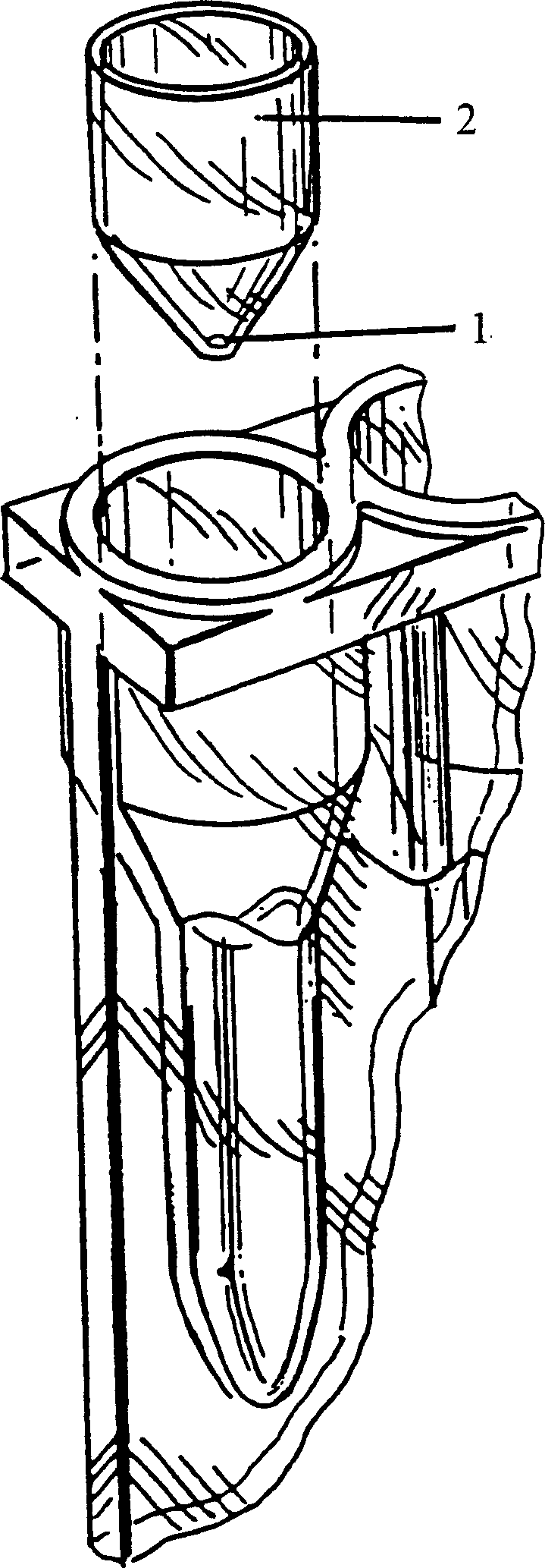
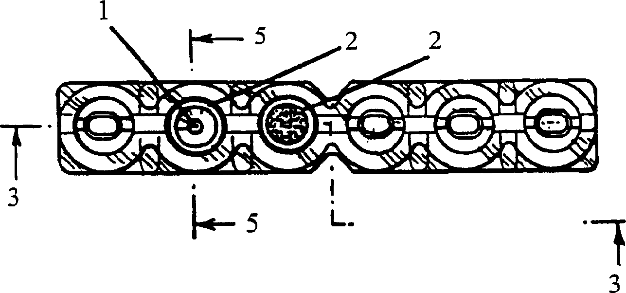
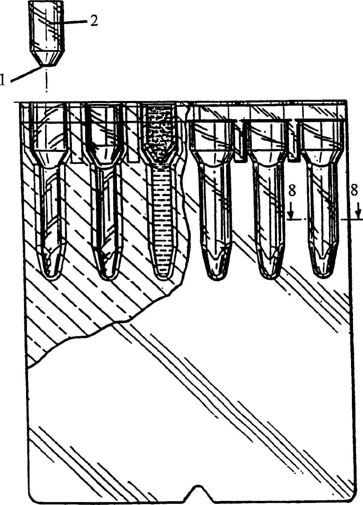
[0072] Will BIOVUE with plugin TM Columns were compared to columns without inserts in order to determine the effectiveness of each configuration for maintaining the spatial air barrier separating the reactants from the separation matrix during incubation. Utilize an insert with a 0.040 inch hole. 40 microliters of buffer was added to each of the 840 columns used in the experiment. The pipette was artificially used at an angle of approximately 45° to the vertical axis of the column in order to deliver the 40 microliters of solution. The column was then observed to determine if an air gap was maintained beneath the reaction chamber. Table 1 gives the number of "leaks out".
[0073] Number of experiments
example 2
[0075] Reagents were also added to the columns (with and without inserts) and incubated at 37°C for 10 minutes. To each of the 480 columns used in the test, 40 microliters of buffer, 40 microliters of serum and 10 microliters of erythrocyte suspension were added. Use the pipette at an angle of approximately 45° to pipette the reagents. After a period of incubation, the column is checked to determine whether an air gap remains under the reaction chamber. Table 2 gives the "leakage" frequencies.
[0076] Number of experiments
example 3
[0078] Fill the column with 40 microliters of buffer with an automatic pipette at an angle of approximately 45°. Automatic pipettes typically use higher transfer forces than manual methods. Observations were made after filling to determine whether an air gap remained under the reaction chamber. Table 3 presents the results for columns with and without inserts.
[0079] Number of experiments
PUM
| Property | Measurement | Unit |
|---|---|---|
| diameter | aaaaa | aaaaa |
| diameter | aaaaa | aaaaa |
| diameter | aaaaa | aaaaa |
Abstract
Description
Claims
Application Information