Cabinet air-conditioner with multi-directional air-blowing

An air conditioner, multi-directional technology, applied in heating mode, air-conditioning system, space heating and ventilation, etc., can solve the problem of lack of multi-directional, omni-directional air supply, little improvement in indoor airflow organization, and inability to air conditioners on the left and right sides. and rear ventilation

An air conditioner, multi-directional technology, applied in heating mode, air-conditioning system, space heating and ventilation, etc., can solve the problem of lack of multi-directional, omni-directional air supply, little improvement in indoor airflow organization, and inability to air conditioners on the left and right sides. and rear ventilation

CN1580661AInactive Publication Date: 2005-02-16SHANGHAI JIAO TONG UNIV

Image

  • Cabinet air-conditioner with multi-directional air-blowing
  • Cabinet air-conditioner with multi-directional air-blowing

Examples


Embodiment Construction

[0008] The specific implementation of the present invention will be further described below in conjunction with the accompanying drawings.

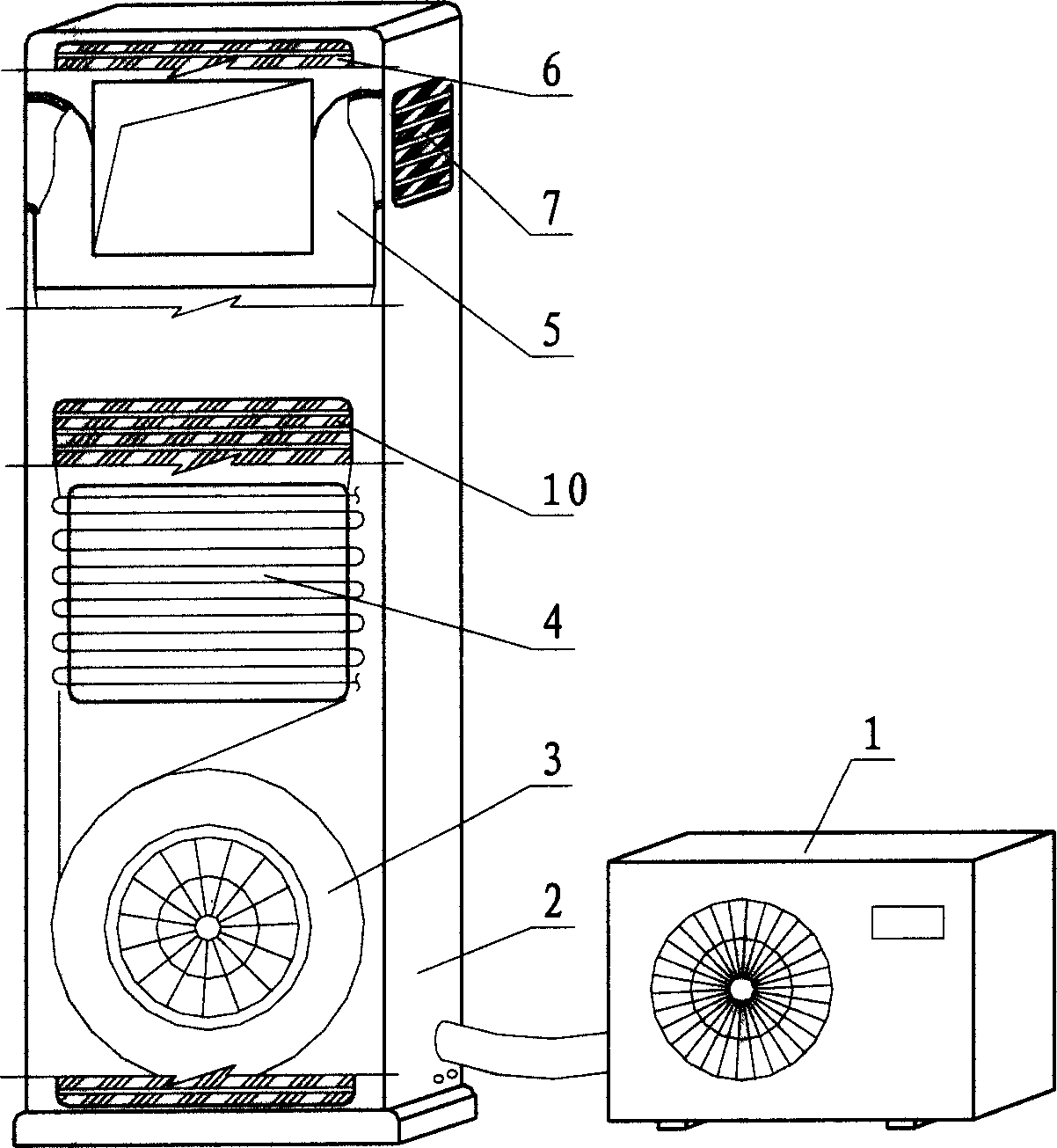
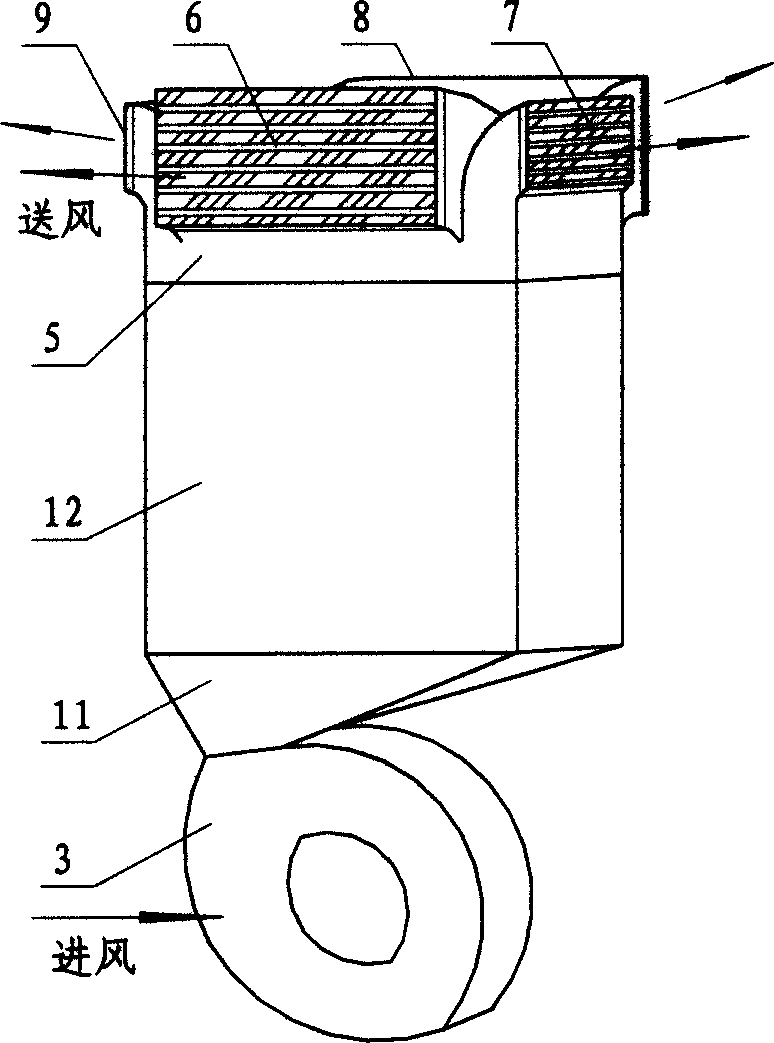
[0009] Such as figure 1 with figure 2 As shown, the present invention includes an air-conditioning outdoor unit 1, an air-conditioning indoor unit 2, a fan 3, an evaporator 4, four ventilation ducts 5, a front air supply port 6, a right air supply port 7, a rear air supply port 8, and a left air supply port 9. Air inlet 10, reducing pipe 11 and air duct 12.

[0010] The air inlet 10 is arranged under the panel of the air conditioner indoor unit 2, the front air supply port 6, the right air supply port 7, the rear air supply port 8 and the left air supply port 9 are respectively arranged on the four surfaces of the upper part of the air conditioner indoor unit 2 casing. 3. The four air passages 5, the reducing pipe 11 and the air pipe 12 are arranged inside the air conditioner indoor unit 2, the evaporator 4 is installed in the air pipe...


PUM


Abstract

This is a multidirectional blower air conditioner. It contains outdoor set, indoor set, blower, evaporator, four-side pass way, front blow outlet, bak blow outlet, right-side blow outlet, left-side blow outlet, blow inlet, change-diameter pipe, and blow-pipe. On the top part of indoor set cover at the front back, right and left side, all install the blow outlet, and increase blow pipe and four-sides pass way. The evaporator is installed inside of the blowpipe. The air pass through evaporator and four-sides pass way, to realize multidirectional blow in the room, to make the indoor air-more gentle, and more evenly.

Description

technical field [0001] The invention relates to a cabinet-type air conditioner, in particular to a cabinet-type air conditioner capable of multi-directional air supply according to user needs, and belongs to the technical fields of building environment and equipment engineering, and air-conditioning and refrigeration engineering. Background technique [0002] A good indoor air-conditioning environment is mainly determined by factors such as reasonable airflow organization and temperature distribution. The current air conditioner has a single air supply mode, simple air flow organization, and poor temperature field balancing ability, which cannot meet the needs of modern family rooms with large areas. The key to solving this problem is that the air conditioner adopts a multi-directional air supply method to create a comfortable indoor environment. [0003] In the existing technology, the application number is 01144980.2, and the invention patent named "air conditioner and it...

Claims


Application Information

Patent Timeline
16 Feb 2005
Publication
CN1580661A
IPC
F24F1/00; F24F13/06; F24F13/20
Inventors
叶晓江; 连之伟