
Connector and a connector system

一种连接器、终端接头的技术,应用在连接、连接装置的零部件、运输和包装等方向,能够解决短路终端7缺少支撑、不能够防止向后移动、位置和锁定突出部分的个数在结构限制等问题

Inactive Publication Date: 2005-04-06
SUMITOMO WIRING SYST LTD
View PDF1 Cites 12 Cited by
  • Summary
  • Abstract
  • Description
  • Claims
  • Application Information

AI Technical Summary

Problems solved by technology

Therefore, although the forward movement of the short-circuit terminal 7 can be prevented, it cannot be prevented from moving backward.
In addition, since the locking protrusion 8 is formed by removing the mold from the front and rear mold-removal holes 6A, if it is desired to provide a plurality of locking protrusions 8 at the front and rear positions, then the position and locking protrusion The number of sections is structurally limited
Consequently, the shorting terminal 7 lacks support with sufficient force within the male housing 1 and thus there is a risk of movement or disengagement when engaged with the male terminal fitting 4 and the canceling portion

Method used


Image

  • Connector and a connector system
  • Connector and a connector system
  • Connector and a connector system

Examples


no. 1 example

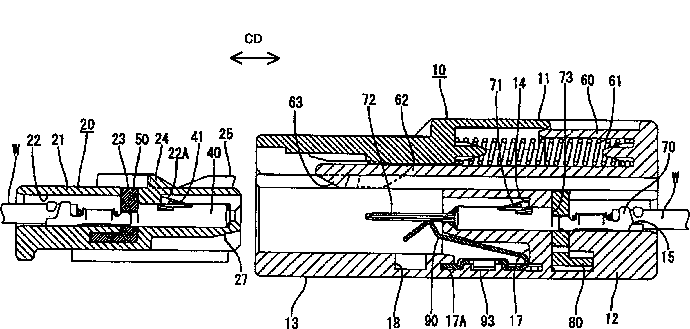
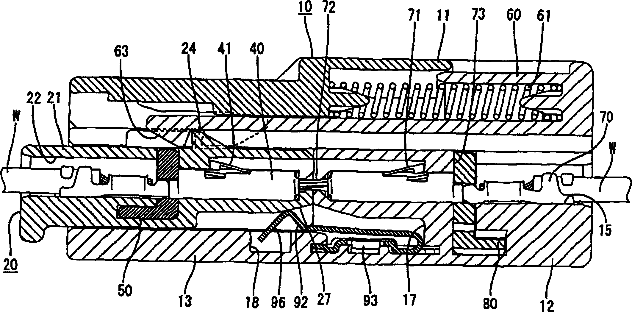
[0054] refer to figure 1-8 The first preferred embodiment of the present invention will be described. A connector used, for example, in an air bag actuation circuit mounted in a motor vehicle is described in the first preferred embodiment. The connector is preferably a male connector 10 and forms at least a part of the airbag actuation circuit by connecting with a female connector 20 (corresponding to a preferred mating connector). In the following description, the mating side of the male and female connectors 10, 20 is referred to as the front side.

[0055] First, the female connector 20 will be described. The female connector 20 has a female housing made of synthetic resin, for example, and its shape is substantially as figure 1 The one on the left is block-shaped, and one or more (preferably a plurality (three in this embodiment)) cavities pass through the female housing 21 substantially side by side along the front-rear direction. One or more female terminal fittings ...

no. 2 example

[0075] Figure 9 (B) shows a second preferred embodiment of the present invention. Although the second embodiment is the same as the first embodiment in that the anchor mounting hole 16 is formed in one side surface of the male housing 11 extending along the connecting direction, it is the same as the first embodiment in the bottom plate 94 of the short-circuit terminal 90 and The receiving portion 17E is different in structure.

[0076] Specifically, the shorting terminal 90 of the second embodiment has an inclined portion 100 inclined upward or inward toward a deformation space from one end of the bottom plate 94 (the side where the folded portion 95 is placed) to the other end.

[0077] The inclined portion 100 has a pointed portion 100A at a position close to the other end of the bottom plate 94 and a locking portion 93 formed at a central position thereof. The engaging piece 98 preferably extends substantially horizontally (connection direction CD) from the pointed port...


PUM


Abstract

An object of the present invention is to securely hold a shorting terminal. An accommodating chamber 17 for accommodating a shorting terminal 90 for shorting male terminal fittings 70 is provided inside a male housing 11. A retainer mount hole 16 communicating with the accommodating chamber 17 and permitting the entrance of the shorting terminal 90 into the accommodating chamber 17 is formed in one side surface of the male housing 11 extending along a connecting direction. The accommodating chamber 17 is provided with a first and a second engaging portions 17A, 17B for holding a base plate 94 of the shorting terminal 90 while positioning it at its front and rear positions with respect to the connecting direction.

Description

technical field [0001] The present invention relates to a connector and connector system with short-circuit terminals. Background technique [0002] Japanese Unexamined Patent Application Publication No. 2003-217764 is a connector of the above-mentioned type. This connector is provided with a female housing and a male housing, wherein the male housing 1 includes a terminal accommodating portion 2 and a socket 3 located in front of the terminal accommodating portion 2 and protruding forward, as shown in FIG. 10 . A cavity 5 into which a plurality of male terminal fittings 4 is inserted passes through the terminal accommodating part 2 in the front-rear direction and a short-circuit terminal accommodating chamber 6 is formed above the cavity 5 in the rear end surface of the jack 3. open mouth. Before the male and female housings are connected to each other, the short-circuit terminal 7 elastically contacts each male terminal fitting 4 to short-circuit a pair of adjacent male ...

Claims


Application Information

Patent Timeline
Patent Type & Authority Applications(China)
IPC IPC(8): B60R21/16H01R13/703H01R31/08
CPCH01R13/7032H01R13/7033H01R31/08
Inventor 中村英人
Owner SUMITOMO WIRING SYST LTD
Features
  • Generate Ideas
  • Intellectual Property
  • Life Sciences
  • Materials
  • Tech Scout
  • Unparalleled Data Quality
  • Higher Quality Content
  • 60% Fewer Hallucinations
Learn More