Objective lens driving device

A driving device and a technology for an objective lens, which are applied in the field of objective lens frames, can solve the problems of difficulty in achieving high speed, difficulty in objective lenses, and reduced acceleration sensitivity, and achieve the effects of achieving high speed, realizing double speed, and improving acceleration sensitivity.

Inactive Publication Date: 2005-06-01
MITSUMI ELECTRIC CO LTD
View PDF2 Cites 2 Cited by
  • Summary
  • Abstract
  • Description
  • Claims
  • Application Information

AI Technical Summary

Problems solved by technology

Although this asymmetric type can improve the acceleration sensitivity, it is very difficult to avoid unnecessary resonance such as roll, pitch, or yaw of the objective lens.
[0028] On the other hand, if it is formed into a symmetric (Synmetry) formula, although unnecessary resonance will not easily occur, the acceleration sensitivity in the focus and tilt directions will decrease, and it will be difficult to achieve high speed.

Method used


Image

  • Objective lens driving device
  • Objective lens driving device
  • Objective lens driving device

Examples


Embodiment Construction

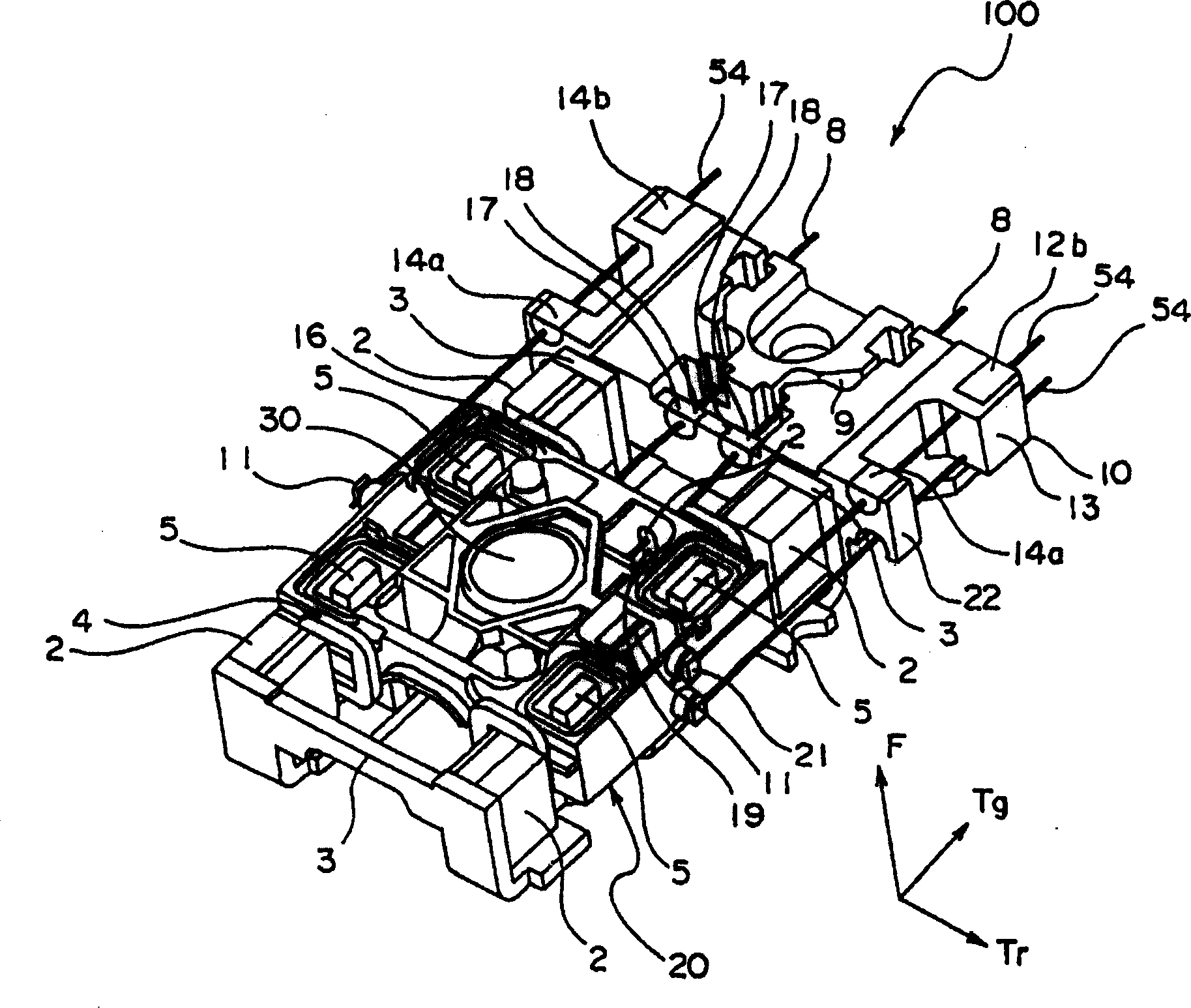
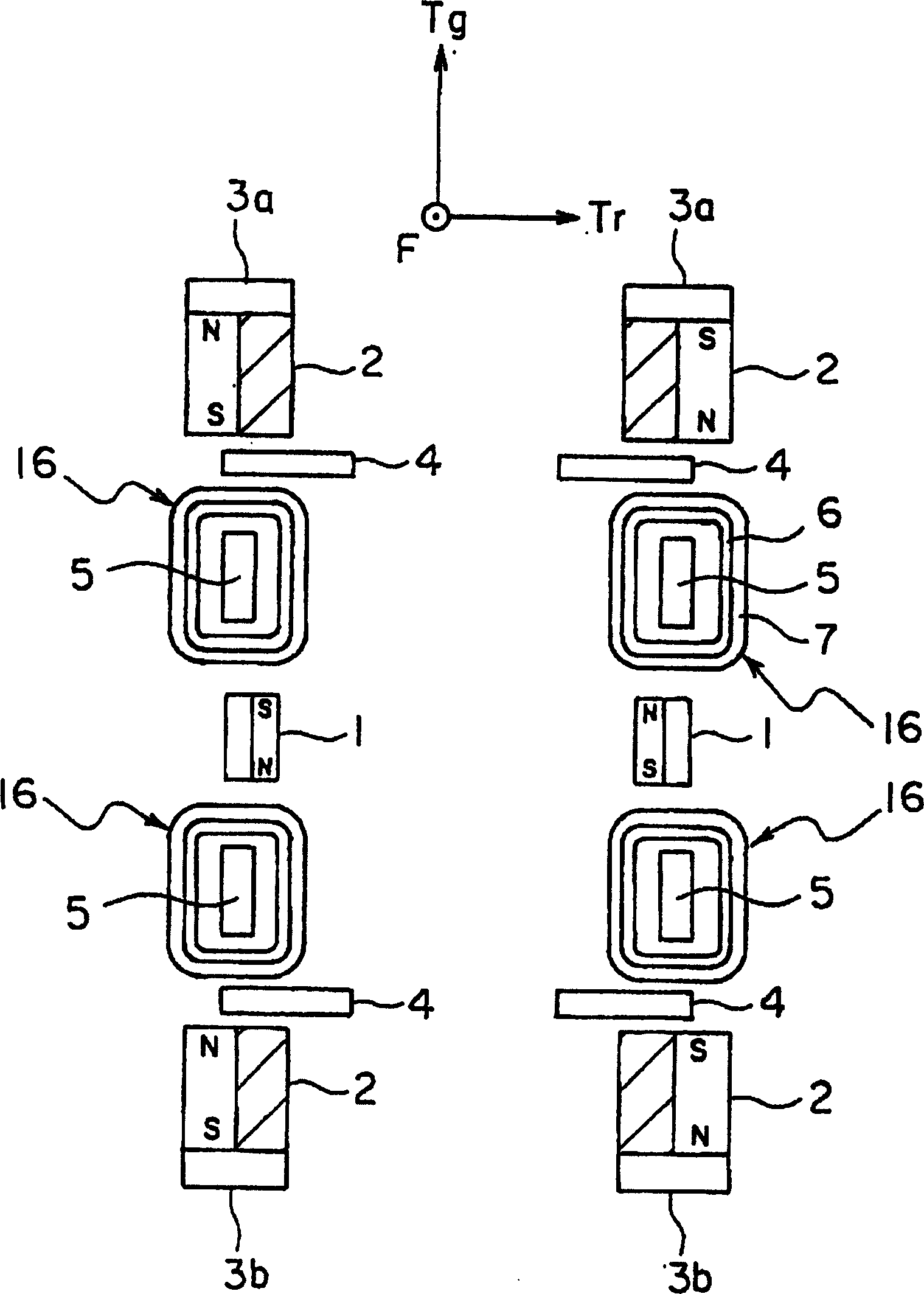
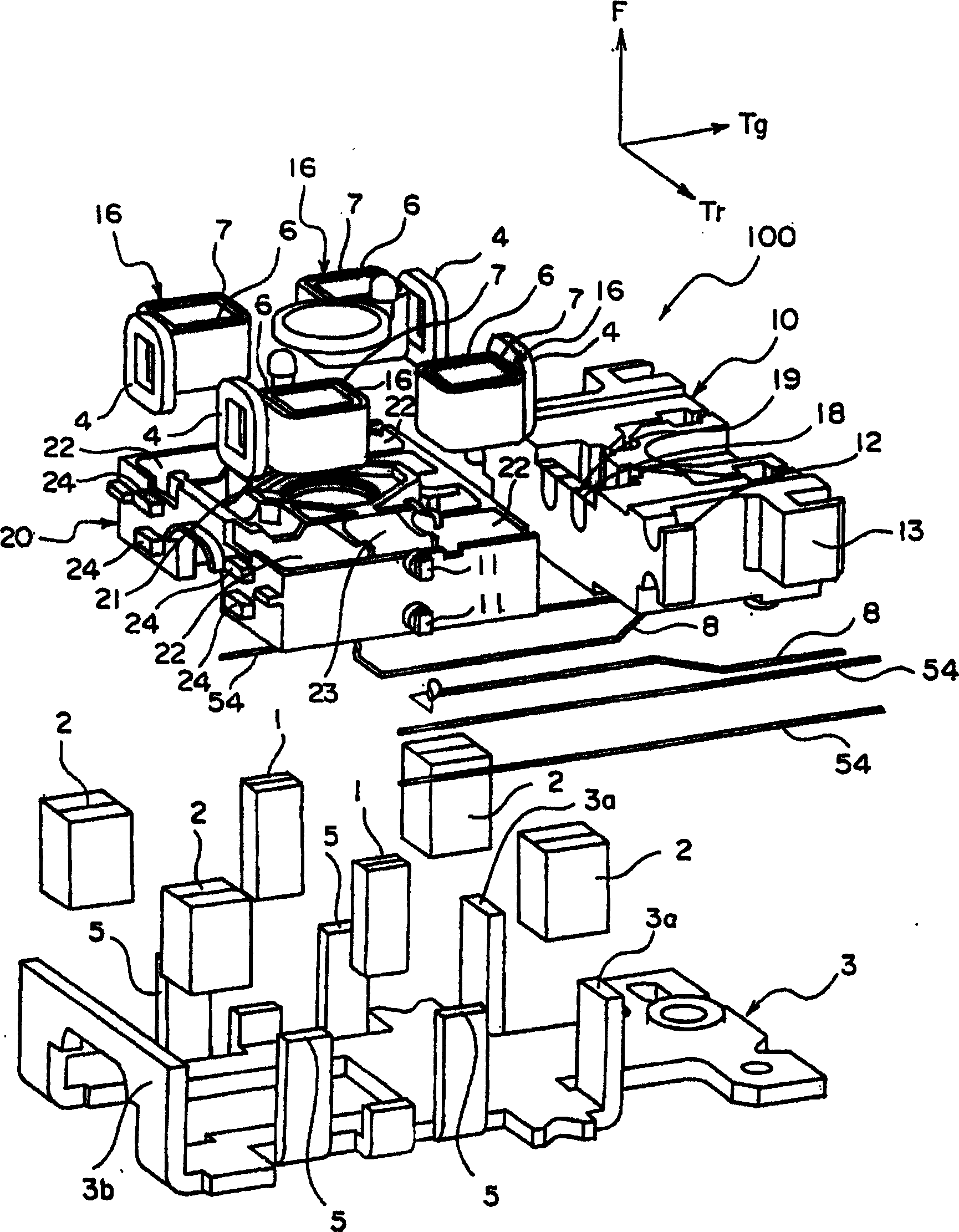
[0051] figure 1 It is a perspective view of the objective lens driving device of the embodiment of the present invention. in addition, figure 2 is showing figure 1 A schematic plan view of the main part of the objective lens actuator shown. image 3 from above figure 1 An exploded perspective view of the objective lens actuator shown. Figure 4 from below figure 1 An exploded perspective view of the objective lens actuator shown.

[0052] like Figures 1 to 4 As shown, the objective lens driving device 100 has a vibration-damping base 10, an objective lens 30, and an objective lens frame 20. With respect to the vibration-damping base 10, 4 first suspension wires 54, 54, 54, 54 and 2 of the supporting object lens frame 20 can be swung. The second suspension wires 8, 8, the yoke base 3 carrying the vibration-damping base 10 and the objective lens holder 20, and 4 first magnets 2 and 2 second magnets 1 fixed on the yoke base 3.

[0053] This objective lens driving de...


PUM


Abstract

The subject of the present invention is to provide an objective lens driving device, which can increase the acceleration sensitivity in the focus and tilt directions without unnecessary resonance in the driver of the symmetrical objective lens driving device, and can realize high magnification. A kind of objective lens driving device has: objective lens frame; Vibration damping seat elastically supporting above-mentioned objective lens frame by the first suspending wire; Have the coil part (16) of tilting coil (6) and focusing coil (7); Be respectively arranged on above-mentioned objective lens The tracking coil (4) near both ends of the first direction of the frame; in the first direction, at least the above-mentioned coil component (16) is clamped, and it is arranged to connect with the two ends of the above-mentioned first direction of the above-mentioned objective lens frame 2 pairs of four main magnets (2); 2 auxiliary magnets (1) that are respectively sandwiched by the pair of coil components (16) in the first direction.

Description

technical field [0001] The invention relates to an objective lens drive device for an optical pick-up head of an optical disk drive, in particular to an objective lens frame. Background technique [0002] Optical disc drive is used to read the disc (CD, CD-ROM, CD-R, CD-RW, DVD-ROM, DVD+R, DVD-R, DVD-RAM, DVD+RW, DVD-RW, Blu- ray, AOD, etc.), or a device that writes information, etc. This type of optical disc drive has an optical pickup that irradiates laser light onto the optical disc and detects the reflected light in order to read information from the optical disc or write information on the optical disc. [0003] In general, an optical pickup has a laser light source that emits a laser beam, an optical system that guides the emitted laser light to an optical disc, and guides the reflected light to a photodetector. Therefore, the optical system includes an objective lens disposed facing the optical disc. [0004] In order to accurately focus laser light on a rotational...

Claims


Application Information

Patent Timeline
Patent Type & Authority Applications(China)
IPC IPC(8): G11B7/00G11B7/085G11B7/09G11B7/095G11B7/135
CPCG11B7/0933G11B7/0935G11B7/0956G11B7/09G11B7/095G11B7/085
Inventor 山田司
Owner MITSUMI ELECTRIC CO LTD
Why Eureka
Try Eureka