Three-phase compensation dynamic reactive power compensation device

A three-phase co-compensation and power compensation technology, applied in reactive power adjustment/elimination/compensation, reactive power compensation and other directions, can solve problems such as failure to suppress and filter, lack of overload capability, and sensitivity to system parameters. Achieve the effects of light weight, improved system stability, and high magnetic induction performance

Inactive Publication Date: 2014-01-15
LIUZHOU ELECTRICAL APP RES INST
View PDF7 Cites 2 Cited by
  • Summary
  • Abstract
  • Description
  • Claims
  • Application Information

AI Technical Summary

Problems solved by technology

[0009] The reactive power compensation devices reported in the above public documents still have the following shortcomings: some have complex structures and high costs; some are sensitive to system parameters, and are prone to harmonic voltage amplification or even resonance; When the filter is used at the same time, the output reactive current decreases linearly with the decrease of the bus voltage, and it does not have overload capability; the effect is not very good, and the fundamental suppression and filtering effect cannot be achieved

Method used


Image

  • Three-phase compensation dynamic reactive power compensation device
  • Three-phase compensation dynamic reactive power compensation device
  • Three-phase compensation dynamic reactive power compensation device

Examples


Embodiment 1

[0064] Copper (Cu) 5, niobium (Nb) 1, chromium (Cr) 0.5, silicon (Si) 2, boron (B) 10, iron (Fe) 81.5. Nanomaterials are pressed by powder metallurgy, and the magnetic permeability ui can reach more than 150,000.

Embodiment 2

[0066] Copper (Cu) 6, niobium (Nb) 0.5, chromium (Cr) 1, silicon (Si) 3, boron (B) 12, iron (Fe) 77.5, nano-materials, pressed by powder metallurgy, magnetic permeability ui can be Reach more than 120,000.

Embodiment 3

[0068] Copper (Cu) 7, niobium (Nb) 1.5, chromium (Cr) 1, silicon (Si) 5, boron (B) 15, iron (Fe) 70.5, nano material, pressed by powder metallurgy, magnetic permeability ui can be Reach more than 200,000.

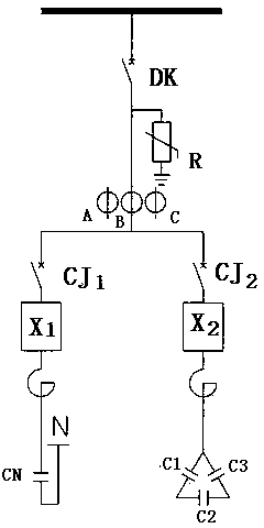
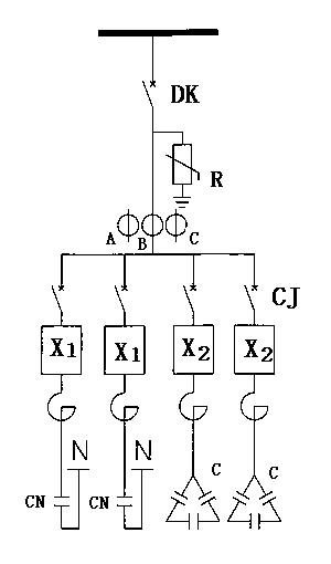
[0069] The three-phase co-compensation dynamic reactive power compensation device can be used in series to meet the needs of different powers. Such as figure 2 .

[0070] The following is figure 1 and figure 2 The dynamic reactive power compensation device needs to be equipped with auxiliary equipment and parameter data charts (see Figure 5 ).


PUM


Abstract

The invention belongs to a three-phase compensation dynamic reactive power compensation device which comprises electric reactors and capacitors, wherein the electric reactors and the capacitors are connected to an A-phase circuit, a B-phase circuit and a C-phase circuit. The three-phase compensation dynamic reactive power compensation device is characterized in that a high-voltage circuit is respectively connected with two paths of electric reactors through the A-phase circuit, the B-phase circuit and the C-phase circuit led by an automatic switch DK via a contactor or a compound switch, an induction coil of one path of the electric reactors is connected with one pole of a single capacitor CN, and the other pole of the single capacitor CN is connected with a zero line; a terminal T1, a terminal T2 and a terminal T3 of an induction coil of the other path of the electric reactors are connected with terminals of a capacitor bank, a delta connection method is adopted in the capacitor bank, the terminal T1 is connected with one pole of the capacitor C1 and one pole of the capacitor C2, the terminal T2 is connected with the other pole of the capacitor C1 and one pole of the capacitor C3, and the terminal T3 is connected with the other pole of the C2 and the other pole of the capacitor C3. The three-phase compensation dynamic reactive power compensation device is used for dynamic reactive power compensation of an electric power system, minimization of injection power harmonic waves can be achieved by controlling, and compared with a traditional dynamic reactive power compensation device, the three-phase compensation dynamic reactive power compensation device has a more ideal comprehensive property.

Description

technical field [0001] The invention relates to a device for eliminating the non-linear load of electric equipment, especially a three-phase co-complementary dynamic reactive power compensation device. Background technique [0002] With the development of the power industry, non-linear loads in the power supply system (frequency conversion device, motor soft start device, magnetic saturation voltage regulator, large rectifier device, communication equipment, medical equipment, electric welding unit, large supermarket lighting, etc.) When these devices are running, the voltage waveform changes and high-order harmonics are generated, which reduces the power factor of the power grid and increases the ripple coefficient f, causing great harm to the power grid, especially capacitors in reactive power compensation circuits. It will amplify the high-order harmonics, causing an inrush current at the moment of closing, the circuit is seriously overloaded, the capacitor is broken down...

Claims


Application Information

Patent Timeline
Patent Type & Authority Applications(China)
IPC IPC(8): H02J3/18
CPCY02E40/30
Inventor 叶金
Owner LIUZHOU ELECTRICAL APP RES INST
Why Eureka
Try Eureka