Apparatus for condensing a drafted fibre sliver

A sliver and fiber technology, applied in the field of a conveyor belt, can solve problems such as defects in the conveyor belt, damage to the compaction effect, etc.

Inactive Publication Date: 2010-10-06
LAKSHMI MACHINE WORKS
View PDF5 Cites 0 Cited by
  • Summary
  • Abstract
  • Description
  • Claims
  • Application Information

AI Technical Summary

Problems solved by technology

On the other hand, after advancing past the pinch rollers, the conveyor belt is in a "thrust" state, so there is a danger of exceeding the length, which is adjusted in time, possibly extending into the Defective support on the upper pair of conveyor belts
However, this creates a situation in which air can penetrate laterally between the conveyor belt and the sliding surface and can impair compaction

Method used


Image

  • Apparatus for condensing a drafted fibre sliver
  • Apparatus for condensing a drafted fibre sliver
  • Apparatus for condensing a drafted fibre sliver

Examples


Embodiment Construction
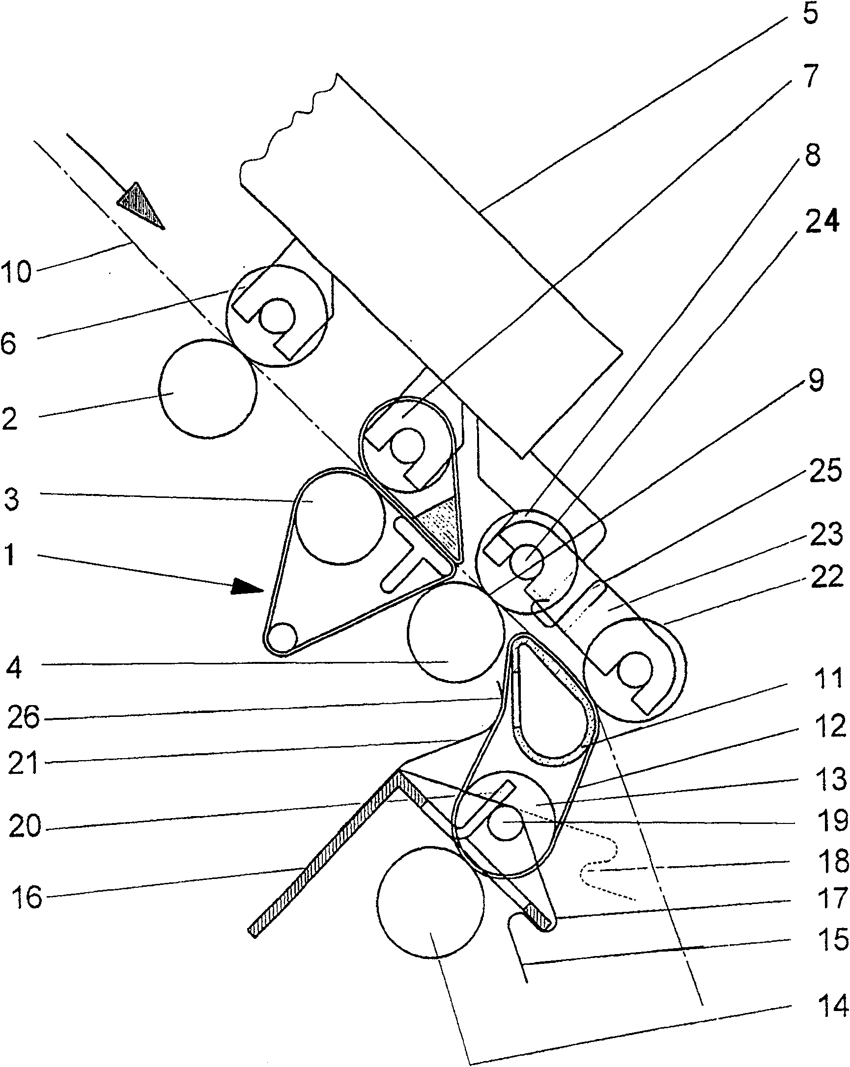
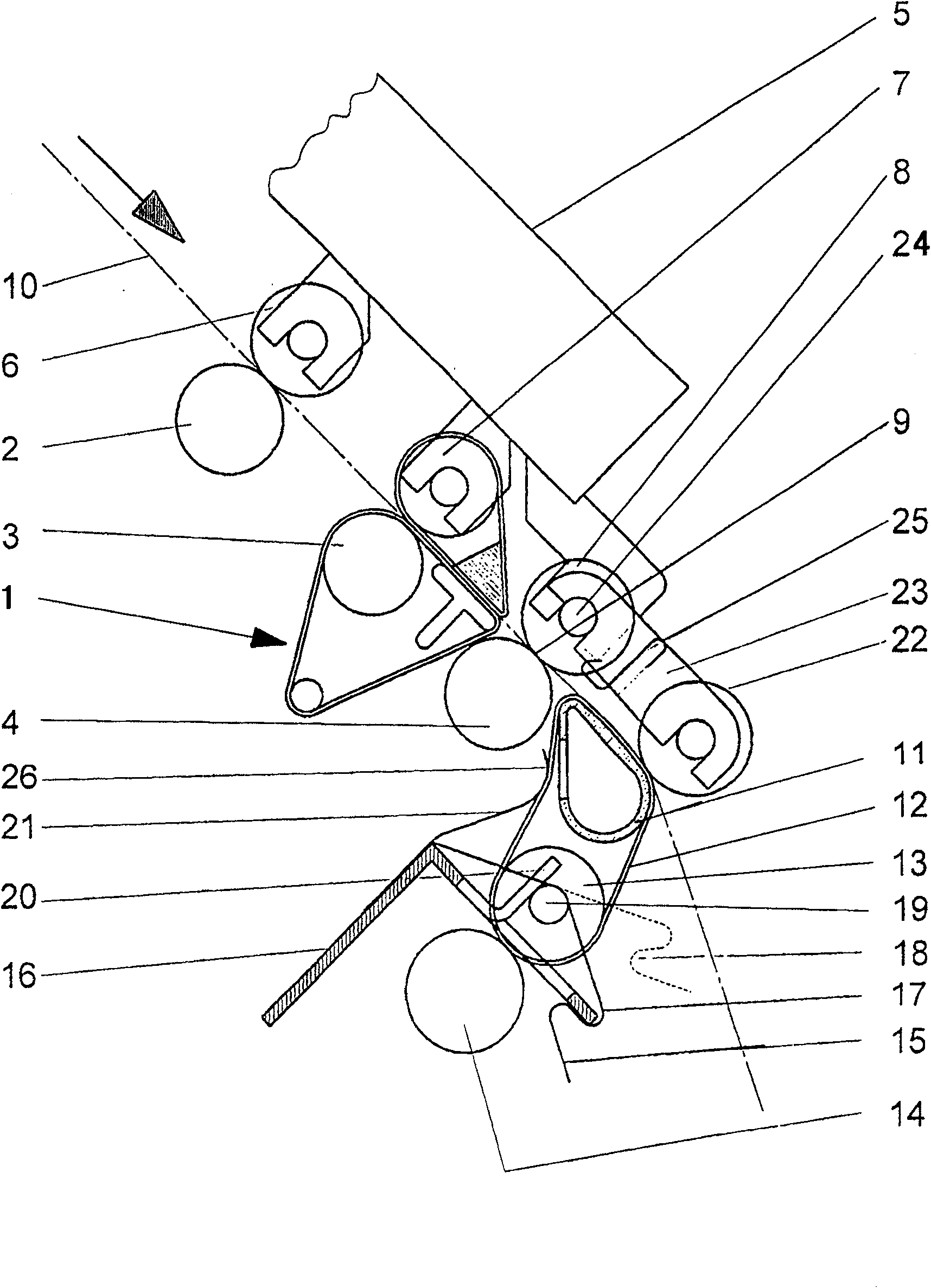
[0024] figure 1 The outlet area of ​​a drafting element 1 is shown, which is used on a ring spinning machine. Three driven lower rollers 2, 3 and 4 are arranged on a shaft (not shown), and three rollers 6, 7 and 8 beside them are contained in a pressure arm 5 and driven. The lower roller 4 and the upper roller 8 jointly form a front roller pair 9 on the drafting element 1 . The drafting of the fed fiber sliver 10 takes place in the drafting unit 1 up to the front roller pair 9, and this is a well-known process.

[0025] The compaction zone with the air extraction element 11 , which is connected to the front roller pair 9 , will be described in detail below. Both the suction element 11 and a guide roller 13 are partially surrounded by an air-permeable conveyor belt 12 . At the portion covered by the conveyor belt 12, a guide roller 13 is pressed against a drive roller 14, which is connected to a motor drive unit (not shown). The drive roll 14 and the lower rolls 2, 3 and 4 ...


PUM

PropertyMeasurementUnit
Shore hardnessaaaaaaaaaa

Abstract

Apparatus for condensing a drafted fibre sliver in a condensation area after the front roller pair on a drafting unit, where the condensation zone contains a suction element with a sliding surface with at least one suction slit essentially running in the direction of movement of the fibre sliver and a transport belt, which transports the fibre sliver over the sliding surface and which is at leastair-permeable over parts of its surface, characterized by the following features: the transport belt (12), apart from the suction element (11), partially loops round a guide roller (13) placed at a distance from the suction element and flexibly arranged transversely on its axis of rotation, the guide roller (13) in the looping area and the transport belt (12) bear against a drive roller (14) and these are provided with the means to create a defined contact pressure between the guide roller (13) and the drive roller (14).

Description

technical field [0001] The invention relates to a device for compacting a drawn fiber sliver in a compacting area behind a front roller pair of a drafting unit, wherein the compacting area comprises an air extraction element with A sliding surface with at least one suction slit arranged on top in the direction of movement of the fiber sliver, and a conveyor belt which transports the fiber sliver over the sliding surface and at least parts of its surface are Breathable. [0002] The invention can be used on spindle spinning machines, especially on ring spinning machines. Background technique [0003] Such devices are known, for example from document no. DE 19903531A1. The suction element has a sliding surface on the same side as the fiber sliver travels, is arched in the direction of fiber travel, and is provided with a suction slot. An air-permeable conveyor belt moves across the sliding surface, transporting the fiber sliver. Below the suction element, the conveyor belt...

Claims


Application Information

Patent Timeline
Patent Type & Authority Patents(China)
IPC IPC(8): D01H1/22D01H5/26D01H1/02D01H5/86D01H5/18D01H5/72
CPCD01H1/025D01H1/22D01H5/72D01H5/26D01H5/86
Inventor 巴尔特·约翰尼斯海因里希·汉斯-尤尔根施瓦贝·伯恩哈德施普罗德·彼得
Owner LAKSHMI MACHINE WORKS
Why Eureka
Try Eureka