Common control method of electronic switch and no-zero-line multiposition electronis switch

A control method and electronic technology, applied in the direction of electronic switches, electrical components, pulse technology, etc., can solve the problem of cumulative rise of load standby voltage and achieve reliable performance, strong adaptability, and easy installation

A control method and electronic technology, applied in the direction of electronic switches, electrical components, pulse technology, etc., can solve the problem of cumulative rise of load standby voltage and achieve reliable performance, strong adaptability, and easy installation

CN1658502AInactive Publication Date: 2005-08-24GUANGDONG SOBEN ELECTRIC ELECTRICAL APPLIANCES

Image

  • Common control method of electronic switch and no-zero-line multiposition electronis switch
  • Common control method of electronic switch and no-zero-line multiposition electronis switch
  • Common control method of electronic switch and no-zero-line multiposition electronis switch

Examples


Embodiment Construction

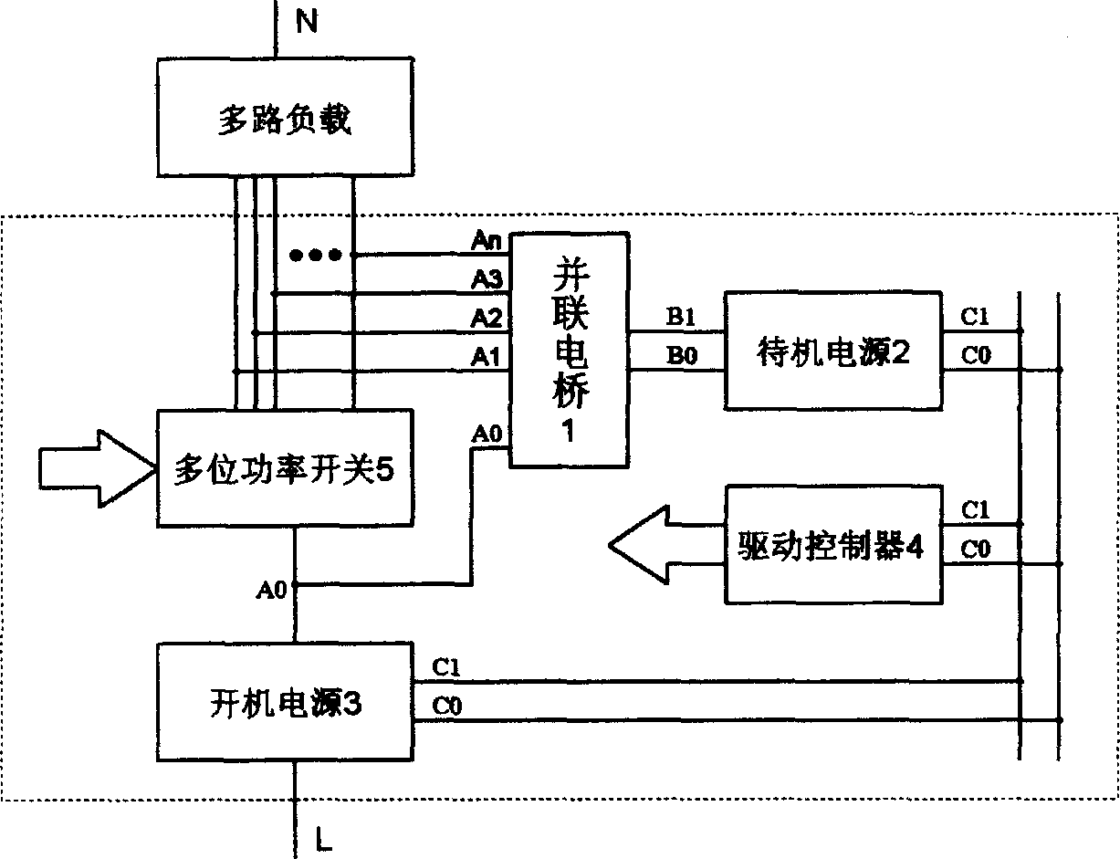
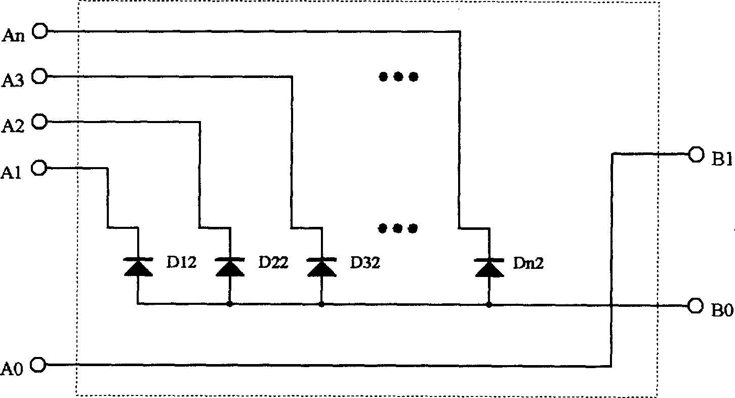
[0031] according to figure 1 The common control method of the electronic switch shown in the figure is to control multiple loads or lines through the standby power supply 2, the start-up power supply 3, the drive controller 4 and the multi-position power switch 5, the start-up power supply 3 supplies power to the drive controller 4, and the standby power supply 2 supply power to the drive controller 4, the drive controller 4 controls the multi-position power switch 5 to turn on and off, and controls the corresponding load circuit, the standby power supply 2 takes power from the standby load circuit, and the start-up power supply 3 takes power from the start-up load circuit. The standby power supply 2 is preferably connected to both ends of the multi-position power switch 5 through a parallel bridge 1 to take power from each standby load circuit; L share power from each start-up load circuit.

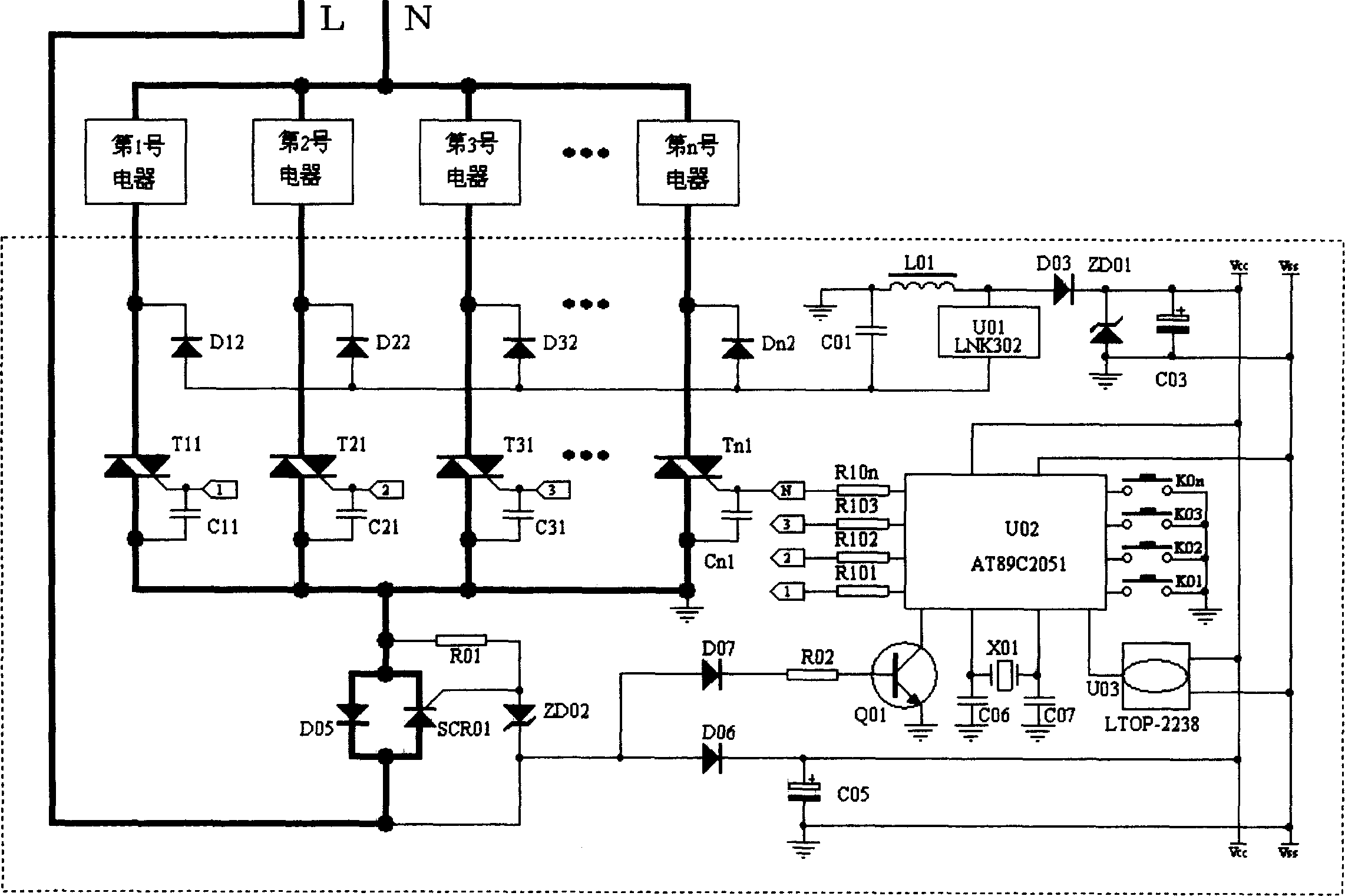
[0032] according to figure 2The non-zero line multi-position electronic switch sp...


PUM


Abstract

This invention relates to a common control method of electronic switch and non zero line multidigit electronic switch. It uses stand-by power, boot-strap power, driving controller and multidigit power switch to control multichannel loading or circuit. The boot-strap power supplies power to the driving controller, the stand-by power supplies power to the driving controller, the multidigit power switch of the driving controller controls the corresponding loading circuit. The characteristic is: the stand-by power gets the electricity from the stand-by loading loop, the boot-strap power receives the electricity from the boot-strap loading loop. The stand-by power connects the two ends of the multidigit power switch through parallel bridge, the boot-strap power series connects between the common end and the front line of the multidigit power switch. This invention greatly simplifies the circuit. It is reliable and reduces the cost. It avoids the expansion of loading failure problem and solves the problem of stand-by voltage accumulation, eliminates the flickering of fluorescent lamp. It is widely used and easily equipped.

Description

Technical field [0001] The invention relates to a control technology of an electronic switch, in particular to a common control method of an electronic switch and a zero-line multi-position electronic switch designed according to the method. Background technique [0002] With the improvement of living standards, people use more and more electrical appliances. There are many types of these electrical appliances, and their characteristics vary greatly. Some of their working conditions are simple and some are complicated, and the requirements for control switches are also different. The traditional one is a mechanical switch. When building wiring, only two wires, one in and one out, are usually reserved. One is the live wire, the other is the load wire, and there is no neutral wire. In order to ensure the safe, convenient use and normal work of electrical appliances, the requirements for various controls (such as: combination control, sequence control, scene control, etc.) and ...

Claims


Application Information

Patent Timeline
24 Aug 2005
Publication
CN1658502A
IPC
H03K17/00; H03K17/72
Inventors
余文松; 何锦荣