Coating pressure feed roller, roller coating device, curved-surface operable roller coating device, automated coating apparatus using those devices, and coating method
A technology of coating device and supply roller, which is applied to the device and coating of surface coating liquid, can solve the problems of difficulty in automation, uniform application of roller brush, labor cost and working time expansion, etc., to prevent device failure, The effect of beautiful coating
- Summary
- Abstract
- Description
- Claims
- Application Information
AI Technical Summary
Problems solved by technology
Method used
Image

Examples
no. 1 approach
[0295] First, an embodiment of the first invention will be described below.
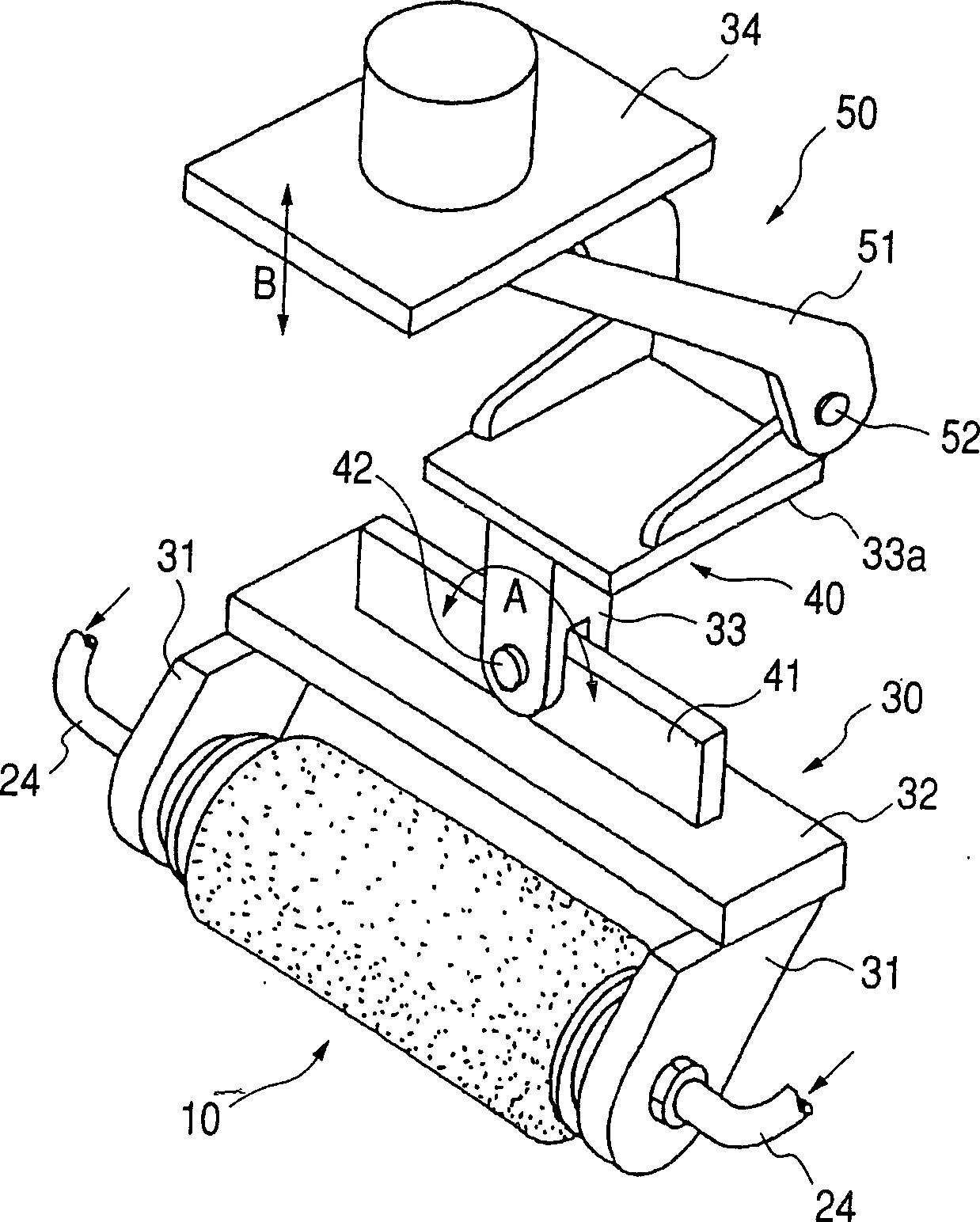
[0296] figure 1 It is a perspective view generally showing a coating apparatus including a pressure supply roller for coating as a first embodiment of the present invention. exist figure 1 Among them, the pressure supply roller for coating according to the first embodiment of the present invention is a part of the roller brush assembly 10 .
[0297] First, the pressure supply roller for coating according to the first embodiment of the present invention will be described below.
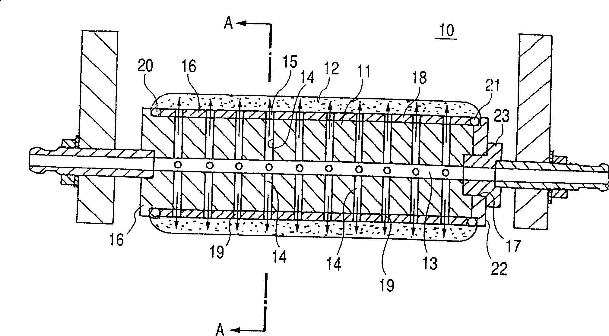
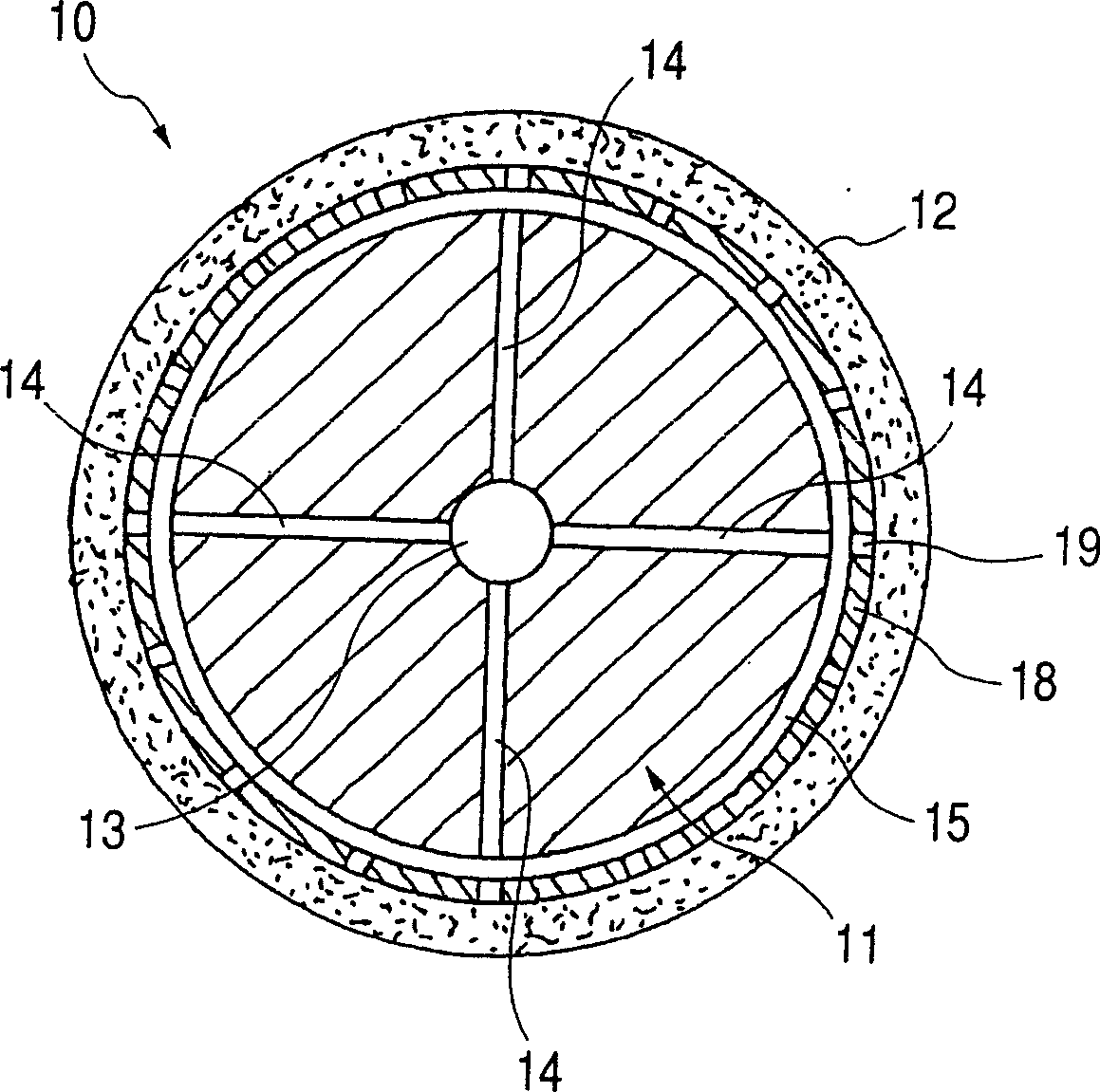
[0298] figure 2 is a longitudinal sectional view showing the roller brush assembly viewed in the axial direction. image 3 for along figure 2 A cross-sectional view taken along line A-A in .
[0299] Such as figure 2 with 3 The roller brush assembly 10 shown includes a solid cylindrical body 11 and a roller brush 12 attached to the outer circumference of the solid cylindrical body 11 in an assembled manner.
[0...
no. 2 approach
[0311] Next, a second embodiment of the present invention will be described.
[0312] The second embodiment concerns the way of feeding the paint to the axial center hole 13 of the solid cylindrical body 11 comprising a pressure feed roller for coating and the way of supporting the solid cylindrical body 11 .
[0313] as combined Figure 29 As mentioned, in a conventional roller coating device, the paint is delivered to the roller from one end of the roller, and the roller is supported in the manner of a cantilever beam. Therefore, the conventional roll coater has the disadvantages as described above. In the current embodiment, the paint pressure supply tube 24 (see figure 1 ) is connected to both ends of the axial center hole 13 of the solid cylindrical body 11. The coating pressure supply roller is rotatably supported at both ends by arms 31 , and these arms 31 are connected together by a lower frame 32 , thereby forming a support 30 .
[0314] Paint pressure supply pipe...
no. 3 approach
[0318] Next, a third embodiment of the present invention will be described.
[0319] Such as figure 1 As shown, the coating device of the third embodiment includes a rotatable support mechanism 40 for rotating the support member 30 supporting the roller brush assembly 10 in the direction of arrow A, and for making the roller brush assembly rotate along the arrow A The vertically movable support mechanism 50 that moves vertically in the direction of B.
[0320] This support 30 comprises two arms 31 and a lower frame 32 bridging between those arms. The two arms 31 rotatably support the roller brush assembly 10 between them. The support 30 is mounted on a rotatable support mechanism 40 , and the rotatable support mechanism 40 is mounted on a vertically movable support mechanism 50 .
[0321] The rotatable support mechanism 40 is constructed such that the plate 41 extends on the upper surface of the lower frame 32 parallel to the axis of the roller brush assembly 10 . The pla...
PUM
 Abstract
Description
Claims
Application Information
 - R&D
- Intellectual Property
- Life Sciences
- Materials
- Tech Scout
- Unparalleled Data Quality
- Higher Quality Content
- 60% Fewer Hallucinations
Browse by: Latest US Patents, China's latest patents, Technical Efficacy Thesaurus, Application Domain, Technology Topic, Popular Technical Reports.
© 2025 PatSnap. All rights reserved.Legal|Privacy policy|Modern Slavery Act Transparency Statement|Sitemap|About US| Contact US: help@patsnap.com