

Reinforcing tab for movable connector and movable connector using the same
A technology of connectors and lead plates, which is applied to the parts, connections, electrical components, etc. of the connection device, and can solve the problems of insufficient strength and damage of the fixed shell
- Summary
- Abstract
- Description
- Claims
- Application Information
AI Technical Summary
Problems solved by technology
Method used
Image

Examples
Embodiment Construction
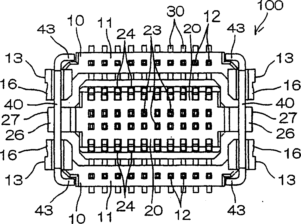
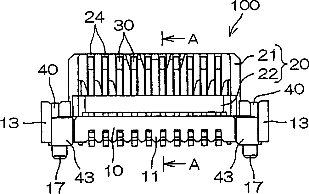
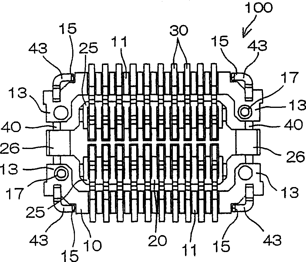
[0023] Fig. 1(a) is a top view of a movable connector according to an embodiment of the present invention, Fig. 1(b) is a front view thereof, Fig. 1(c) is a bottom view thereof, and Fig. 1(d) is a right side view thereof . in addition, figure 2 It is a partial perspective view of the above-mentioned movable connector, FIG. 3(a) is a side view showing a state of use, and FIG. 3(b) is a cross-sectional view showing the same state of use.
[0024] FIG. 1( a ) shows a plan view looking down on the mounting surface (surface on which the movable connector is mounted) of the wiring substrate when the movable connector is mounted on the wiring substrate. In the following description, the mounting surface side of the wiring board (the lower side in FIG. 1( b )) will be described below.
[0025] In addition, in the drawings, the movable connector is shown with a size larger than the actual size, but the actual size of the movable connector is about 6 mm in width, about 12 mm in length...
PUM
 Abstract
Description
Claims
Application Information