

Pinch detection device and opening/closing device
A technology for detecting equipment and traps, which is used in door/window fittings, transportation and packaging, building construction, etc., and can solve problems such as object damage
- Summary
- Abstract
- Description
- Claims
- Application Information
AI Technical Summary
Problems solved by technology
Method used
Image

Examples
no. 1 example
[0029] refer to Figures 1(a) to 6 The invention of the first embodiment will be described.
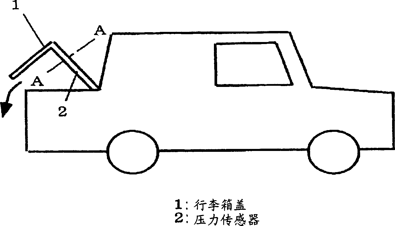
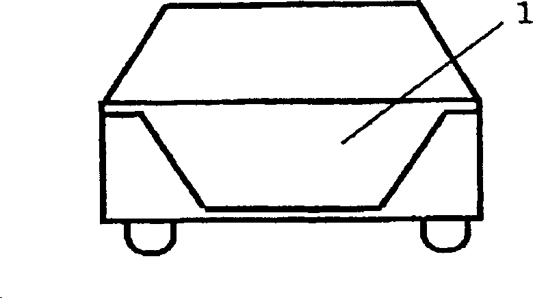
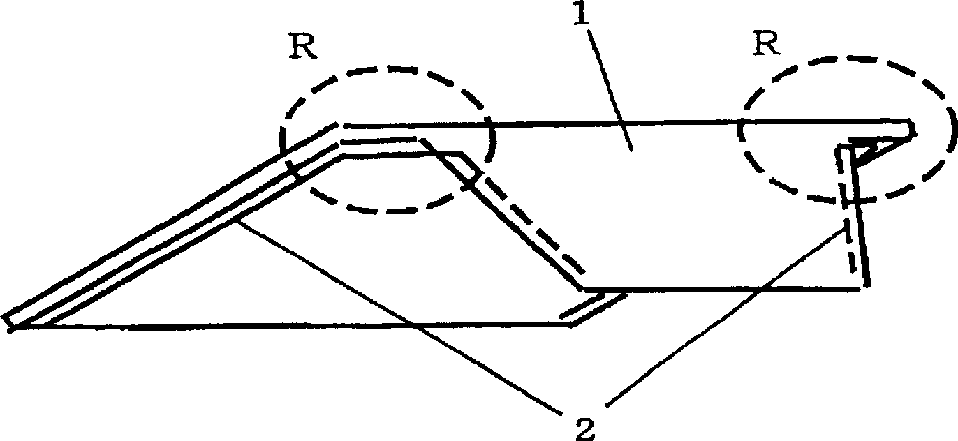
[0030] FIG. 1( a ) is an external view (showing a state where the trunk lid is opened) of the entrapped object detection device and the opening / closing device of the first embodiment invention as seen from the side direction of the vehicle body, and FIG. 1( b ) is External views of the same equipment seen from the rear of the vehicle body (showing a state where the trunk lid is closed), two views showing the structure in which the pressure sensor 2 is provided on the trunk lid 1 of the vehicle. FIG. 2 is an external view showing the installation position of the pressure sensor 2 on the trunk lid 1 , where the trunk lid 1 is shown from the inside of the vehicle. Fig. 2 (a) shows the state that the pressure sensor 2 is arranged on each side of the right and left sides of the trunk lid 1, and Fig. 2 (b) shows a single pressure sensor 2 along the left and right sides of the trunk lid 1 a...
no. 2 example
[0053] will refer to the attached Figure 7(a) with 7(b) The invention of the second embodiment will be described. 7(a) and 7(b) show a cross-sectional view of the pressure sensor 2 of the pinch detection device and the invention of the second embodiment; wherein FIG. 7(a) shows that a predetermined load is not applied to the pressure sensor 2 7( b ) shows a state where a predetermined amount or more of a load is applied thereby compressing the pressure sensor 2 .
[0054] The second embodiment differs from the first embodiment in that the pressure sensor 2 includes a nonlinear flexible member 8 whose deformation with respect to the load is nonlinear, and in that the piezoelectric sensor 8 is disposed adjacent to the nonlinear flexible member 28 . For example, a thin steel strip or reinforced resin having a convex shape used in a convex positioning device is used as the nonlinear flexible member 28 . Such a member has a feature of suddenly deforming into a concave shape wh...
no. 3 example
[0058] The invention of the third embodiment will be described below. The difference between the third embodiment and the first and second embodiments is that the object is kept in contact with the pressure sensor 2 according to the signal output from the piezoelectric sensor 8 .
[0059] will refer to Figure 8 The operation according to the above structure will be described. Figure 8 is a characteristic view showing the signal V output by the filter section 19 in the judging device 16 of the third embodiment and the judgment result J output by the inclusion judging section 20 of the same device. exist Image 6 In, V and J sequentially refer to the vertical axis, and the horizontal axis represents time "t". The filtering section 19 employs a structure similar to that in the first and second embodiments.
[0060] Such as Figure 8 As shown, when a part of the pressure sensor 2 of the trunk lid 1 is grasped or loosened by hand, a signal component whose signal component is...
PUM
 Abstract
Description
Claims
Application Information