
An automatic tensioning device for copper bars of traction motors

A technology for traction motors and copper bars, which is applied to electric components, manufacturing motor generators, electromechanical devices, etc., can solve the problems of low work efficiency and high labor intensity of copper bar tensioning operations, so as to reduce labor intensity and improve work efficiency. Effect

Active Publication Date: 2022-07-19
CRRC TANGSHAN CO LTD
View PDF0 Cites 0 Cited by
  • Summary
  • Abstract
  • Description
  • Claims
  • Application Information

AI Technical Summary

Problems solved by technology

[0003] The purpose of the present invention is to provide an automatic tensioning device for copper strips of traction motors, so as to solve the technical problems in the prior art that the copper strip tensioning operation of the motor rotor is labor-intensive and has low work efficiency

Method used


Image

  • An automatic tensioning device for copper bars of traction motors
  • An automatic tensioning device for copper bars of traction motors
  • An automatic tensioning device for copper bars of traction motors

Examples


Embodiment Construction

[0029] In order to make the technical problems, technical solutions and beneficial effects to be solved by the present invention clearer, the present invention will be further described in detail below with reference to the accompanying drawings and embodiments. It should be understood that the specific embodiments described herein are only used to explain the present invention, but not to limit the present invention.

[0030] It should be noted that when an element is referred to as being "fixed to" or "disposed on" another element, it can be directly on the other element or indirectly on the other element. When an element is referred to as being "connected to" another element, it can be directly connected to the other element or indirectly connected to the other element.

[0031] It is to be understood that the terms "length", "width", "upper", "lower", "front", "rear", "left", "right", "vertical", "horizontal", "top" , "bottom", "inside", "outside", etc. indicate the orien...


PUM


Abstract

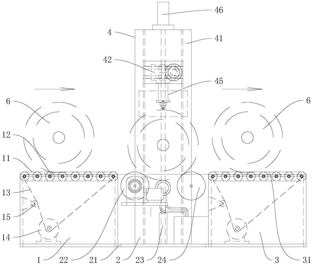
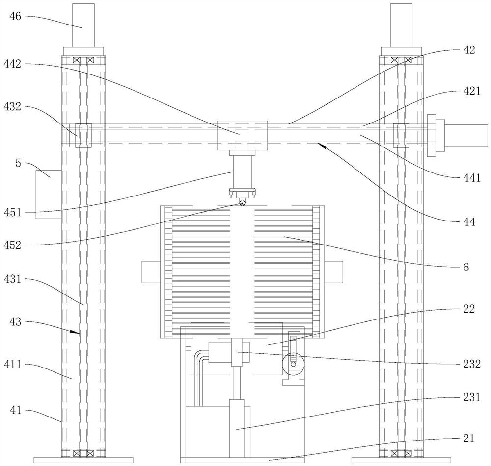
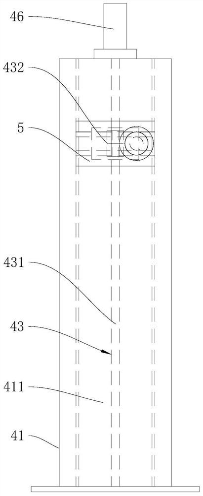
The invention provides an automatic tensioning device for a copper strip of a traction motor, which belongs to the technical field of motor manufacturing and maintenance, and includes a conveying device, a supporting device, a receiving device and a tensioning device. The supporting roller, the driving roller and the supporting roller are respectively arranged close to the conveying device and the receiving device, and the jacking mechanism is used to support the motor rotor to fall on the driving roller and the supporting roller and to lift the motor rotor to the supporting roller and fall on the receiving device , the tensioning device includes a column, a beam, a vertical moving mechanism, a horizontal moving mechanism and a tensioning head. The automatic tensioning equipment for traction motor copper bars provided by the present invention positions and supports the motor rotor by means of driving rollers, support rollers and a jacking mechanism, and the tensioning head is driven by the vertical moving mechanism and the horizontal moving mechanism to move along the length direction of the motor rotor And quickly and reliably complete the extrusion of the copper bar, complete the transportation of the motor rotor, and improve the work efficiency.

Description

technical field [0001] The invention belongs to the technical field of motor manufacturing and maintenance, and more particularly relates to an automatic tensioning device for copper bars of traction motors. Background technique [0002] Rail vehicles, especially high-speed trains, are required to re-tighten the copper bars of the traction motor rotor when overhauling for a certain mileage to ensure mechanical strength. The general process method is to hoist the rotor on the roller, and use a special tensioning air hammer along the rotor groove. The mouth is tightened from both ends of the rotor to the middle, the depth of the tightening indentation is 4.6mm~5.2mm, and the air pressure of the air hammer is 6bar~8bar. The air hammer cannot stop during the movement process. After completing a groove, the copper strip is tightened and then the roller is turned to lower One copper bar is tightened. After all the copper bars are tightened, hoist the motor rotor to the next proces...

Claims


Application Information

Patent Timeline
Patent Type & Authority Patents(China)
IPC IPC(8): H02K15/00H02K15/02
CPCH02K15/00H02K15/02
Inventor 王雪岭唐福旭张志佳杨国军王艳敏商宁吴红星姚明刚高云鹏
Owner CRRC TANGSHAN CO LTD
Learn More