
Uninterruptible power ammeter replacement device

A technology for electric meters and electric energy meters, which is applied to measuring devices, measuring electrical variables, instruments, etc., can solve the problems of difficult replacement, labor and time consumption, and long replacement time, so as to shorten the replacement time, reduce labor costs, and improve The effect of stability

Inactive Publication Date: 2019-08-09
NINGHAI COUNTY POWER SUPPLY BUREAU
View PDF11 Cites 8 Cited by
  • Summary
  • Abstract
  • Description
  • Claims
  • Application Information

AI Technical Summary

Problems solved by technology

[0004] 1. Due to the damage of the electric meter, it is inevitable that the staff need to come to replace the electric meter. The traditional electric meter replacement needs to be powered off, which usually takes 10-15 minutes, which brings a very bad user experience to the user, especially It is in some 24-hour uninterrupted power places, such as Internet cafes, gyms, etc., and it is required not to cut off the power
[0005] 2. It is troublesome to disassemble the traditional electric meter, and there may be wrong wiring. The operator may also touch some live parts during disassembly, which is not conducive to personal safety.
[0006] 3. The imitation stealing design of the traditional electric meter is not in place, and non-operators can open the electric meter themselves, or even disassemble the electric meter and take it away
[0007] 4. The traditional electric meter needs to go to the scene to operate the power on and off, and it cannot be controlled remotely, which is not conducive to management
[0008] In the process of replacing the ammeter when the ammeter is damaged, although it only takes 10-15 minutes to replace the ammeter, compared with some users or places with high electricity requirements, the power outage time is still too long, and even some places require that it cannot be replaced. power failure
The replacement time is too long, the replacement is difficult, and it takes a lot of manpower and time
Traditional meters are not convenient for integrated management

Method used


Image

  • Uninterruptible power ammeter replacement device
  • Uninterruptible power ammeter replacement device
  • Uninterruptible power ammeter replacement device

Examples


Embodiment 1

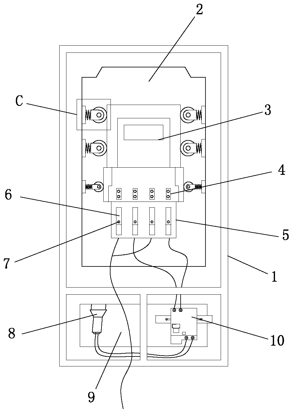
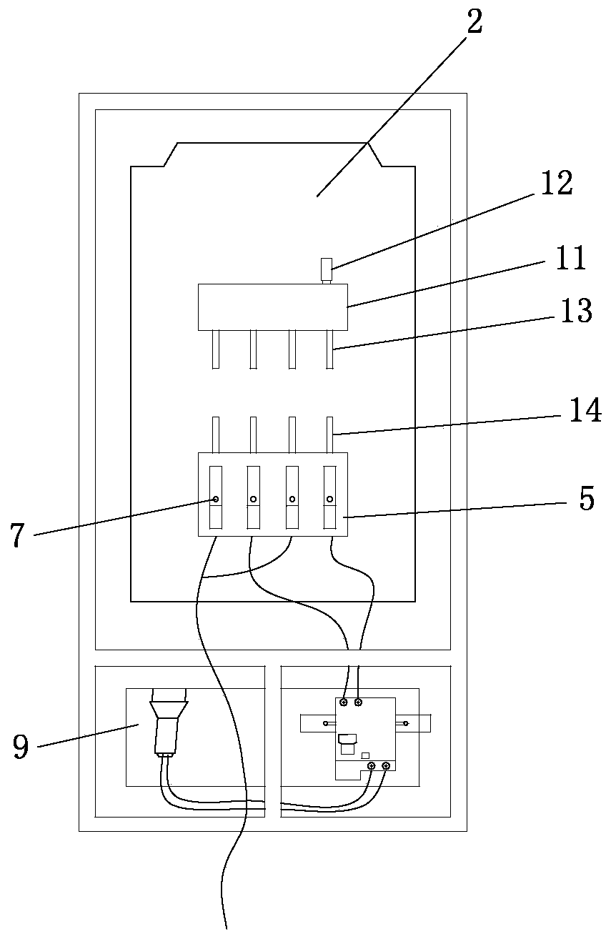
[0039] Such as Figure 1-3 As shown, the present invention provides a non-stop electric meter replacement device, including a meter box 1, a first insulating mounting plate 2 and a second insulating mounting plate 9 are arranged in the meter box 1, and a plug-in electric energy meter is installed on the first mounting plate 2 3. The first mounting plate 2 is also equipped with an electric energy meter adapter 5 that cooperates with the plug-in electric energy meter 3. A plurality of drainage bases 6 are installed on the electric energy meter adapter 5, and a plurality of first drainage bases 6 are installed on the drainage base 6. A safety switch 10 is installed on the second insulating mounting plate 9 , and a lighting lamp 8 is connected to the safety switch 10 . By installing the electric energy meter adapter 5 that cooperates with the plug-in electric energy meter 3 on the first mounting plate 2, the electric energy meter adapter 5 is provided with a drainage base 6 that c...

Embodiment 2

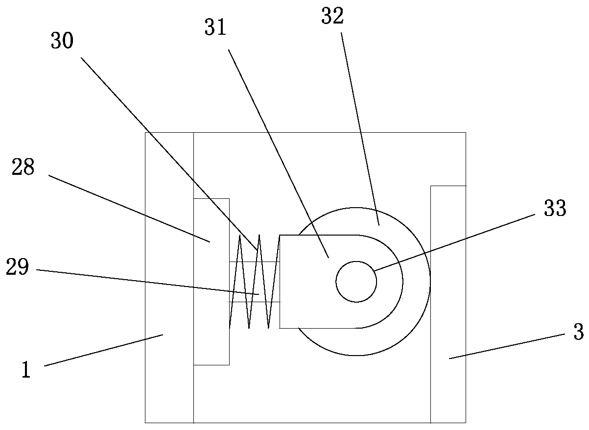
[0044] refer to Figure 4-6 The difference between the second embodiment and the first embodiment is that a mounting groove 16 is provided on the opposite side of the inner wall of the second energization socket 15, and a first piston 17 is installed on the inner wall of the mounting groove 16, and the first piston 17 The first piston shaft 18 is installed on the end away from the plug-in electric energy meter 3, the first installation plate 20 is installed on the side of the first piston shaft 18 away from the first piston 17, and the first rotating shaft is installed on the first installation plate 10 21. A first guide wheel 22 is installed on the first rotating shaft 21. When the plug-in electric energy meter 3 is plugged into the electric energy meter adapter 5, the first guide wheel 22 is arranged in contact with the electric energy meter adapter plug 14. By establishing a mounting groove 16 on the opposite side of the second power jack 15 inner wall, and installing the f...

Embodiment 3

[0049] Such as Figure 7 As shown, the difference between the third embodiment and the first embodiment is that the conductive module 11 is provided with a magnet 27 which is adsorbed on the inner wall of the meter case 1 . The magnet 27 can realize that the conductive module 11 can be adsorbed on the inner wall of the meter box 1 when not in use, which is convenient for daily use when changing the meter.

[0050] It can be understood that the power meter adapter 5 proposed in Embodiment 1 and Embodiment 2 of the present invention adopts a base modeled as ADAPTER, and the plug-in power meter is designed as a separate socket meter, which consists of two parts: the meter and the base. Composition, the base is the base model of ADAPTER proposed by the present invention, which solves the problem that the user cannot use electricity normally when the meter is removed or changed, and realizes that the electric energy meter adapter 5 can be automatically connected when the electric m...


PUM


Abstract

The invention provides an uninterruptible power ammeter replacement device, which comprises a box. The box is internally provided with a first insulating mounting board and a second insulating mounting board; a detachable ammeter is mounted on the first insulating mounting board; an ammeter adapter matched with the detachable ammeter is also mounted on the first mounting board; multiple drainage bases are mounted on the ammeter adapter; the drainage base is provided with multiple first electrified jacks; a safety switch is mounted on the second insulating mounting board; and a lighting lamp isconnected to the safety switch. According to the uninterruptible power ammeter replacement device disclosed in the invention, ammeter replacement is facilitated, the ammeter replacement time is shortened, manual cost for ammeter replacement is reduced, and the ammeter can be prevented from being damaged in the case of ammeter replacement.

Description

technical field [0001] The invention relates to a meter replacement device, in particular to a meter replacement device without power failure. Background technique [0002] With the development of technology and the improvement of management, people's demand for electricity is getting higher and higher, and the requirements for the experience of using electricity are also getting higher and higher. In non-special circumstances, although the user needs to perform power outage processing only when the meter is replaced, it will also bring a bad user experience to the user. [0003] During the traditional meter replacement process, the following situations may occur: [0004] 1. Due to the damage of the meter, it is inevitable that the staff need to come to replace the meter. The traditional replacement of the meter requires power-off processing, which usually takes 10-15 minutes, which brings a very bad user experience to the user, especially It is in some places that operat...

Claims


Application Information

Patent Timeline
Patent Type & Authority Applications(China)
IPC IPC(8): G01R11/02G01R11/04
CPCG01R11/02G01R11/04
Inventor 储海峰朱勇尤锭军陈祥金龚成龙
Owner NINGHAI COUNTY POWER SUPPLY BUREAU
Learn More