Eureka AIR delivers breakthrough ideas for toughest innovation challenges, trusted by R&D personnel around the world.

Additive manufacturing device and method for micro-system three-dimensional structure

An additive manufacturing, three-dimensional technology, applied in the field of additive manufacturing, can solve the problems of uncontrollable wettability, difficult to reach micron-level stepper motor precision, and high cost

Pending Publication Date: 2018-12-21
JILIN UNIV
View PDF7 Cites 8 Cited by
  • Summary
  • Abstract
  • Description
  • Claims
  • Application Information

AI Technical Summary

Problems solved by technology

[0005] (1) Difficulties in the separation of sub-micron microfluids: the current commonly used extrusion or separation methods (piezoelectric method and thermal bubble method) have problems in the injection of ultrafine fluids. The problem is that it is difficult to achieve a small amount of injection less than 1pl liquid
[0006] (2) Droplets cannot be precisely positioned on the working platform: For micron-sized droplets, their precise positioning requires high precision of the position control of the printing platform. A piezoelectric linear platform is required, but its formation range is only tens of microns, and the cost High and the stroke is not suitable for the integrated manufacturing of micro-system devices, and the precision of the stepping motor commonly used in engineering is difficult to reach the micron level, so the large-scale and high-precision positioning of the droplet is an urgent problem to be solved at present
[0007] (3) The wettability of droplets deposited on the forming platform cannot be controlled: Conventional spraying and additive manufacturing cannot control the wettability of droplets finally deposited on the platform, and the spreading of droplets can only be achieved by the kinetic energy during flight. Difficult to make ultra-thin films

Method used


Image

  • Additive manufacturing device and method for micro-system three-dimensional structure
  • Additive manufacturing device and method for micro-system three-dimensional structure
  • Additive manufacturing device and method for micro-system three-dimensional structure

Examples


Embodiment Construction

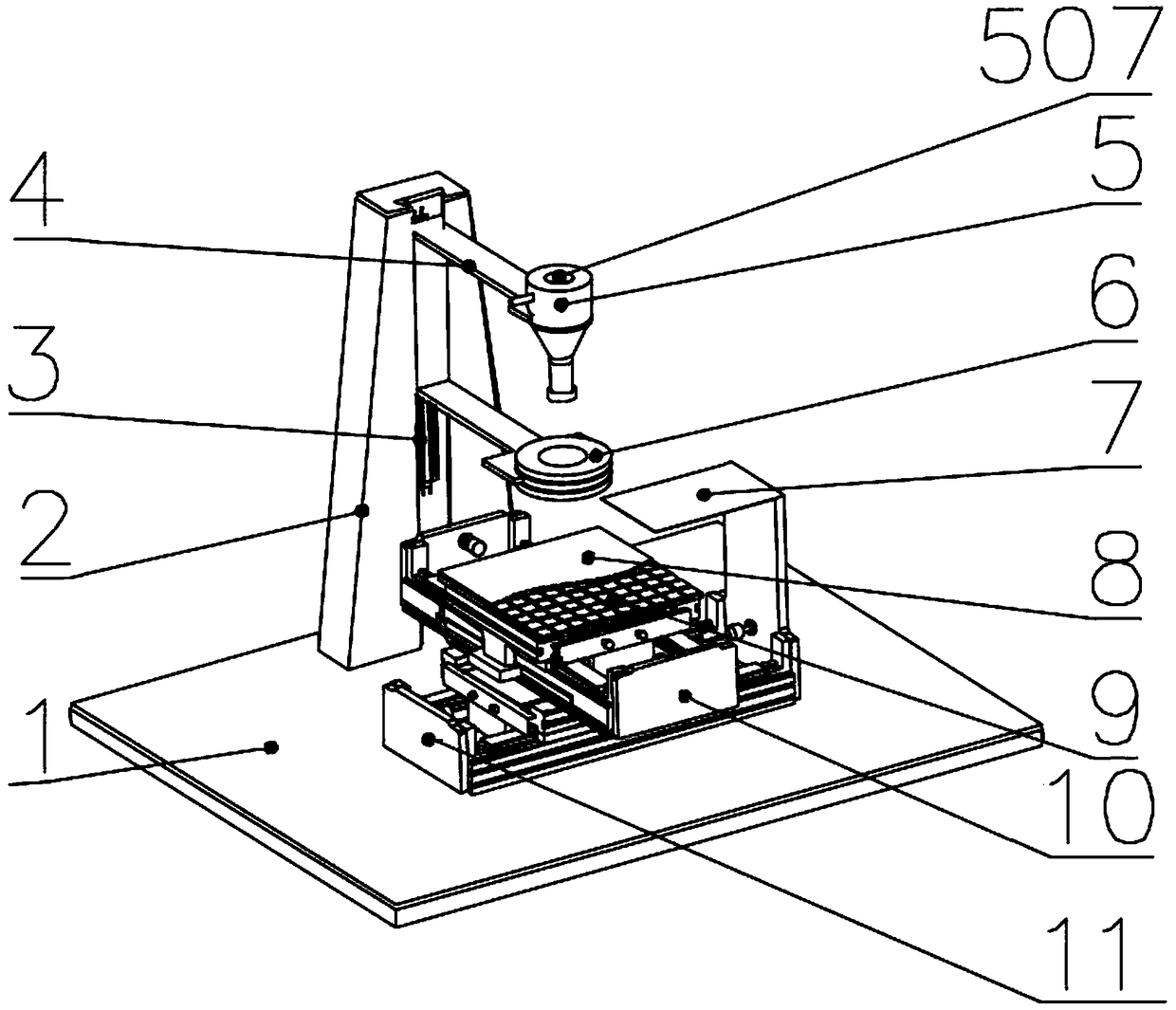
[0043] Such as figure 1 As shown, the high-viscosity droplet extrusion module 5 is fixed on the guide column 2 through the support frame 4, the X-axis moving device 11 is fixed on the base 1, the Y-axis moving device 10 is fixed on the X-axis moving device 11, and the deflection electric field The electrode 6 is installed on the guide column 2 through the Z-axis moving device 3, the dielectric layer 8 is bonded on the electrode array 9, the electrode array 9 is fixed on the Y-axis moving device 10, and the polarization module 7 is fixed on the base 1, And located above the dielectric layer 8 .

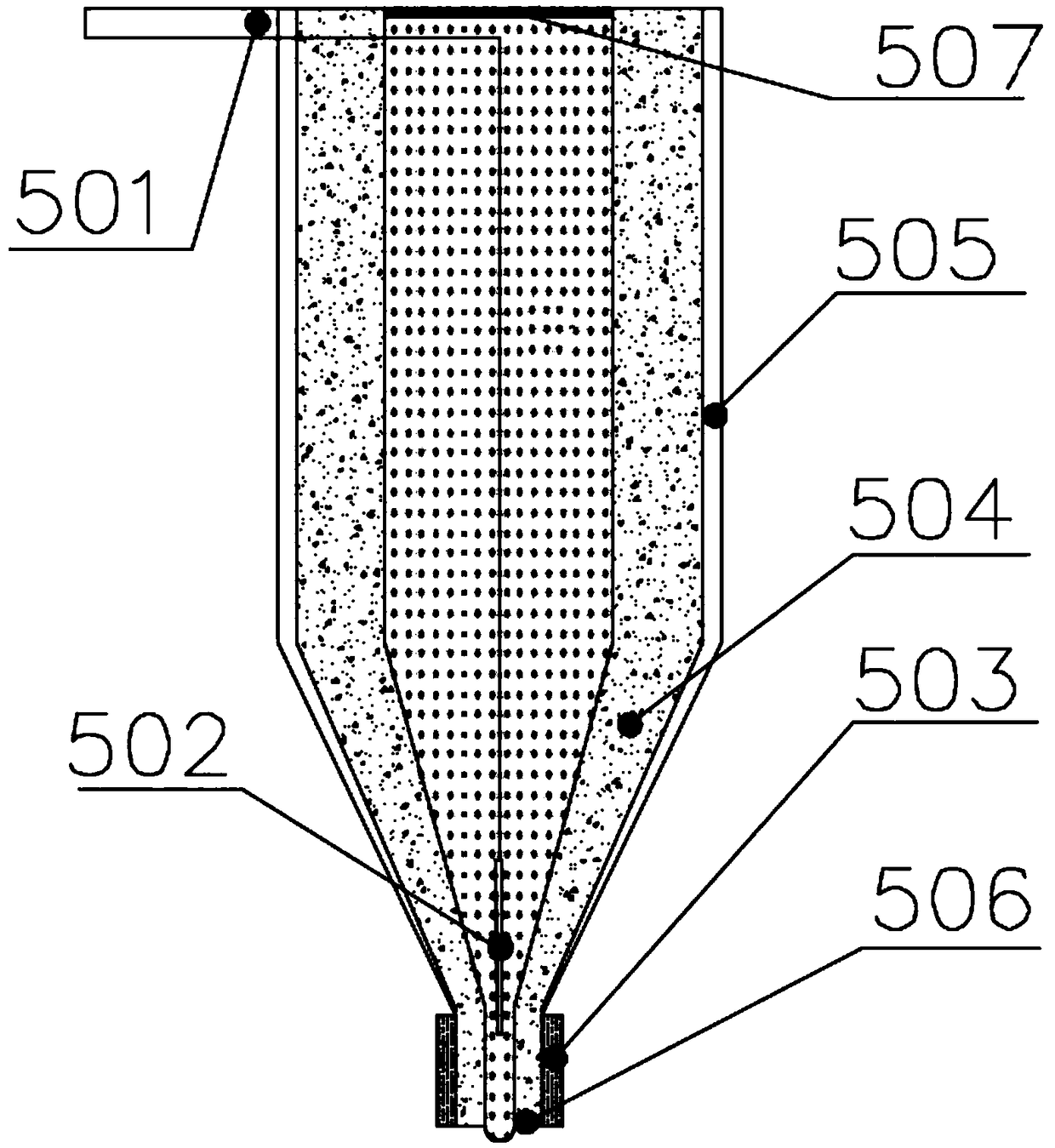
[0044] Such as figure 2 As shown, the high-viscosity droplet extrusion nozzle includes: nozzle housing end 501, electro-hydraulic separation electric field electrode positive electrode 502, electro-hydraulic separation electric field electrode negative electrode 503, stepless variable area heating device 504, nozzle housing 505, forming The microport 506 and the piezoelectric diaphr...


PUM


Abstract

The invention relates to an additive manufacturing device and method for a micro-system three-dimensional structure, and belongs to the field of additive manufacturing. A high-viscosity microdroplet extrusion nozzle is fixed to a guide upright column through a supporting frame, an X-axis moving device is fixed to a base, a Y-axis moving device is fixed to the X-axis moving device, a deflection electric field electrode is installed on the guide upright column through a Z-axis moving device, a dielectric layer adheres to an electrode array, the electrode array is fixed to the Y-axis moving device, and a polarization module is fixed to the base and above the dielectric layer. According to the device and method, a layered manufacturing technology is utilized, the technical characteristic thatliquid material droplets solidify and are formed under a pulsed electric field, and the precise control over additive manufacturing is realized by using a pulsed electric field separation technology.Accurate jetting of the micron-scale droplets is achieved by adjusting voltage parameters so as to achieve high-viscosity liquid high-frequency jetting.

Description

technical field [0001] The invention belongs to the technical field of additive manufacturing, and in particular relates to an additive manufacturing device and method for ultra-thin functional layers with high precision volume control and shape control. Background technique [0002] In recent years, research work in the field of microsystem manufacturing at home and abroad has progressed rapidly, and a large number of research results have been achieved in two-dimensional integration and micro-nano processing. At the level of structural design, the chip-level two-dimensional integration of multiple microsystems at the same time improves the functional density to a certain extent, but the increase in the number of microsystems will lead to a sharp increase in the two-dimensional size of the device. The combination of two-dimensional integrated chips through space optimization forms a three-dimensional structure, which not only improves the space utilization rate but also inc...

Claims


Application Information

Patent Timeline
IPC IPC(8): B29C64/112B29C64/194B29C64/393B33Y30/00B33Y50/00
CPCB29C64/112B29C64/194B29C64/393B33Y30/00B33Y50/00Y02P10/25
Inventor 王东方姜新岩刘睿殷志富万胜来王鼎康
Owner JILIN UNIV
Why Eureka
Eureka Blog
Learn More