An additive manufacturing process for metal parts

A technology of additive manufacturing and metal parts, which is applied in the field of additive manufacturing of metal parts, can solve the problems of low strength of parts, poor tensile strength of metal parts, low material utilization rate, etc., and achieve precise and integrated manufacturing, The effect of high degree of intelligence

Active Publication Date: 2022-06-21
四川三阳激光增材制造技术有限公司
View PDF0 Cites 0 Cited by
  • Summary
  • Abstract
  • Description
  • Claims
  • Application Information

AI Technical Summary

Problems solved by technology

The material utilization rate of LOM technology is low, the tensile strength of the manufactured metal parts is poor, and the surface of the parts has step texture
3DP printing uses the liquid binder sprayed by the nozzle to bond the metal powder laid on the powder bed to form, and the strength of the part is very low

Method used


Image

  • An additive manufacturing process for metal parts
  • An additive manufacturing process for metal parts
  • An additive manufacturing process for metal parts

Examples


Embodiment 1

[0041] refer to figure 1 For example.

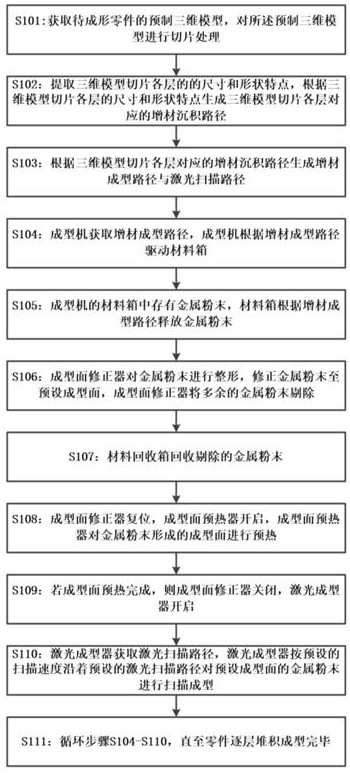
[0042] An additive manufacturing process for metal parts comprising the following steps:

[0043] S101: Acquire a prefabricated three-dimensional model of the part to be formed, and perform slice processing on the prefabricated three-dimensional model.

[0044] S102: Extract the size and shape characteristics of each layer of the three-dimensional model slice, and generate an additive deposition path corresponding to each layer of the three-dimensional model slice according to the size and shape characteristics of each layer of the three-dimensional model slice.

[0045]S103: Generate an additive molding path and a laser scanning path according to the additive deposition path corresponding to each layer of the three-dimensional model slice.

[0046] S104: The molding machine obtains the additive molding path, and the molding machine drives the material box according to the additive molding path.

[0047] S105: Metal powder is stored i...

Embodiment 2

[0055] refer to Figure 2-5 For example.

[0056] As a preferred way of this embodiment, it includes, in step S103, the additive molding path is generated according to the additive deposition path corresponding to each layer of the three-dimensional model slice, and the area of ​​each layer slice of the additive molding path is larger than that of the additive deposition path .

[0057] The range of the additive molding path is larger than that of the additive deposition path. The additive deposition path is the sliced ​​prototype of the metal part, and the additive molding path is the sliced ​​prototype of the additive stacking.

[0058] The laser scanning path coincides with the additive deposition path, and the part slices formed after the laser scans along the laser scanning path are consistent with the additive deposition path.

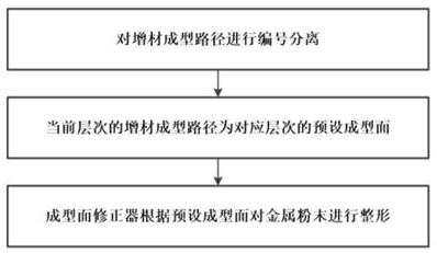
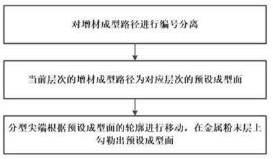
[0059] As a preferred method of this embodiment, it includes: in step S106, the forming surface corrector performs shaping of the metal powder...


PUM


Abstract

An additive manufacturing process for metal parts, comprising the following steps: S101: slice a prefabricated three-dimensional model; S102: generate an additive deposition path corresponding to each layer of the three-dimensional model slice; S103: slice each layer corresponding to the three-dimensional model The additive deposition path generates the additive molding path and the laser scanning path; S104: The molding machine drives the material box according to the additive molding path; S105: The material box releases the metal powder according to the additive molding path; S106: The molding surface corrector controls the metal powder Carry out shaping; S107: The material recovery box recycles the rejected metal powder; S108: The forming surface preheater preheats the forming surface formed by the metal powder; S109: If the forming surface is preheated, the laser former is turned on; S110: Laser forming The laser scan path is acquired by the laser shaper, and the laser shaper scans and shapes the metal powder on the preset molding surface along the preset laser scanning path at a preset scanning speed; S111: loop steps S104‑S110 until the parts are piled up and formed layer by layer .

Description

technical field [0001] The invention relates to the field of additive manufacturing, in particular to an additive manufacturing process for metal parts. Background technique [0002] 3D printing technology is a technology that uses CAD design data to manufacture solid parts by layer-by-layer accumulation of materials. Compared with traditional cutting processing technology, it is a bottom-up material accumulation manufacturing method. Commonly used for prototype or model manufacturing in teaching, mold, aerospace and other neighborhoods. [0003] At present, additive manufacturing represented by 3D printing has become a main process of rapid prototyping. 3D printing technologies for printable metal parts include: LOM (Layered Solid Manufacturing), 3DP (Three-Dimensional Printing), SLS (Selective Laser Sintering), SLM (Selective Laser Melting), LSF (Laser Stereoforming), etc. The LOM forming principle is to use the laser to cut the metal foil of the film material coated wit...

Claims


Application Information

Patent Timeline
Patent Type & Authority Patents(China)
IPC IPC(8): B22F3/105B33Y10/00
CPCB33Y10/00B22F10/00B22F10/73B22F10/28B22F10/366B22F12/13Y02P10/25
Inventor 陆晨晖
Owner 四川三阳激光增材制造技术有限公司
Why Eureka
Try Eureka