A device and method for quickly removing metal sealing rings of small catheters

A technology of metal sealing rings and small conduits, applied in the manufacture of tools, hand-held tools, etc., can solve problems such as hidden dangers in quality, and achieve the effects of prolonging service life, reducing production costs, and reliable extrusion

Active Publication Date: 2019-08-09
CAPITAL AEROSPACE MACHINERY +1
View PDF2 Cites 0 Cited by
  • Summary
  • Abstract
  • Description
  • Claims
  • Application Information

AI Technical Summary

Problems solved by technology

[0011] The purpose of the present invention is to overcome the deficiencies in the prior art, to provide a device and method for quickly taking out the metal sealing ring of small conduits, to adapt to the installation and later maintenance of small conduits in current aircraft, and to solve the problem of existing tooling in taking out metal seals in small conduits. There are hidden quality problems in the sealing ring process

Method used


Image

  • A device and method for quickly removing metal sealing rings of small catheters
  • A device and method for quickly removing metal sealing rings of small catheters
  • A device and method for quickly removing metal sealing rings of small catheters

Examples


Embodiment 1

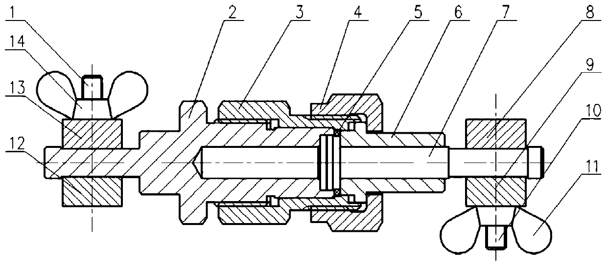
[0072] Take the metal sealing ring at the female end of the small conduit connector such as Figure 7 shown. The convex step combination is matched with the female end 17 of the small conduit connector, wherein the end of the small conduit connector is inlaid with a metal sealing ring 5, and the female end 17 of the small conduit connector is held by an open-end wrench, and the tooling outer nut 4 is tightened clockwise with another open-end wrench , and a torque of 50N·m is applied. At this time, the metal sealing ring is located between the small conduit joint and the top shaft 6, and is deformed under pressure. hook structure such as Figure 10 shown. Then loosen the tooling overcoat nut 4 with a wrench, pull the pull shaft 7 out by pulling the pull plate assembly, and the metal sealing ring is pulled out. At this time, loosen the wing nuts 11, 14, and separate the upper pressing block 9 and the lower pressing block 8, so that the drawing plate assembly can be separated ...

Embodiment 2

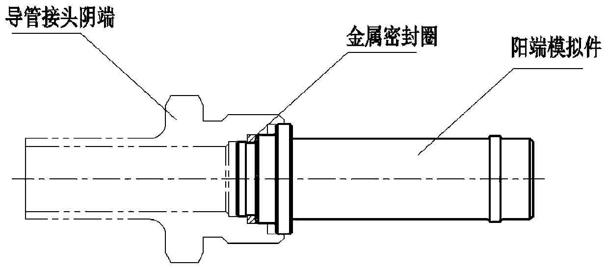
[0074] Take the metal sealing ring at the male end of the small conduit connector such as Figure 8 shown. The concave step combination is matched with the male end 16 of the small conduit joint, wherein the small conduit joint end is inlaid with a metal sealing ring 5, and the pull sleeve 3 is held by an open-end wrench, and the small conduit male end is tightened clockwise with the jacket Nut 15, and apply a 50N·m torque, at this time, the metal sealing ring is located between the small conduit joint and the top sleeve 2, deformed under pressure, the outer diameter of the metal sealing ring becomes larger, and embedded in the hole-shaped ring hook of the pull sleeve 3, Hole ring hook structure such as Figure 9 shown. Then loosen the overcoat nut 15 at the male end of the small conduit with a wrench, and pull the pull sleeve 3 out by pulling the pull plate assembly, and the metal sealing ring is pulled out. At this time, the wing nuts 11 and 14 are loosened, and the upper...


PUM


Abstract

The invention relates to a device and method for rapidly taking out a metal sealing ring from a small duct. The device comprises a convex step combination and a concave step combination. The convex step combination consists of a tool coat nut, an ejector shaft, a pull shaft and a pull plate combination, and the concave step combination consists of an ejector sleeve, a pull sleeve and a pull platecombination. Each pull plate combination comprises an upper pressing block, a lower pressing block, a butterfly nut and a stud. When the metal sealing ring is inlaid in a female end of a joint of thesmall duct, the convex step combination is used for taking out the metal sealing ring in the joint of the duct; and when the metal sealing ring is inlaid in a male end of the joint of the small duct,the concave step combination is used for taking out the metal sealing ring in the joint of the duct. By the device, the metal sealing ring which is inlaid in any of the female end and the male end ofthe joint of the small duct can be taken out rapidly, the metal sealing ring can be nondestructively separated from the device, production efficiency of installation and maintenance of the small ductis improved, quality risks are reduced, and potential quality hazards are eliminated.

Description

technical field [0001] The invention relates to a device and a method for quickly taking out a metal sealing ring of a small catheter, belonging to the field of mechanical structure design. Background technique [0002] Modern aircraft use a large number of pipelines, and some pipelines use metal sealing rings. During the product assembly process and product maintenance, it is inevitable to replace the metal sealing rings in the small conduit joints. In the process of replacing the metal sealing ring of the small conduit, since the metal sealing ring is firmly embedded in the small conduit joint due to extrusion deformation, it is very important to protect the sealing surface of the small conduit joint, which determines the later pipeline of the product Sealing has a great impact on the quality of aircraft products. Since the small catheter joint has a female end and a male end, after the small catheter joint is disconnected, the metal sealing ring may be embedded in either...

Claims


Application Information

Patent Timeline
Patent Type & Authority Patents(China)
IPC IPC(8): B25B27/14
CPCB25B27/14
Inventor 王得成雷义姚健厉晓笑陈棣李勇叶炜刘喜强
Owner CAPITAL AEROSPACE MACHINERY
Why Eureka
Try Eureka