

LED device with protective circuit of diode
A technology of light-emitting diodes and diodes, applied in circuits, electrical components, electric solid-state devices, etc., can solve the problems of reduced chip life, inability to effectively screen light-emitting diode chips, damage to light-emitting diode chips, etc., and achieve high reliability.
- Summary
- Abstract
- Description
- Claims
- Application Information
AI Technical Summary
Problems solved by technology
Method used
Image

Examples
Embodiment 1
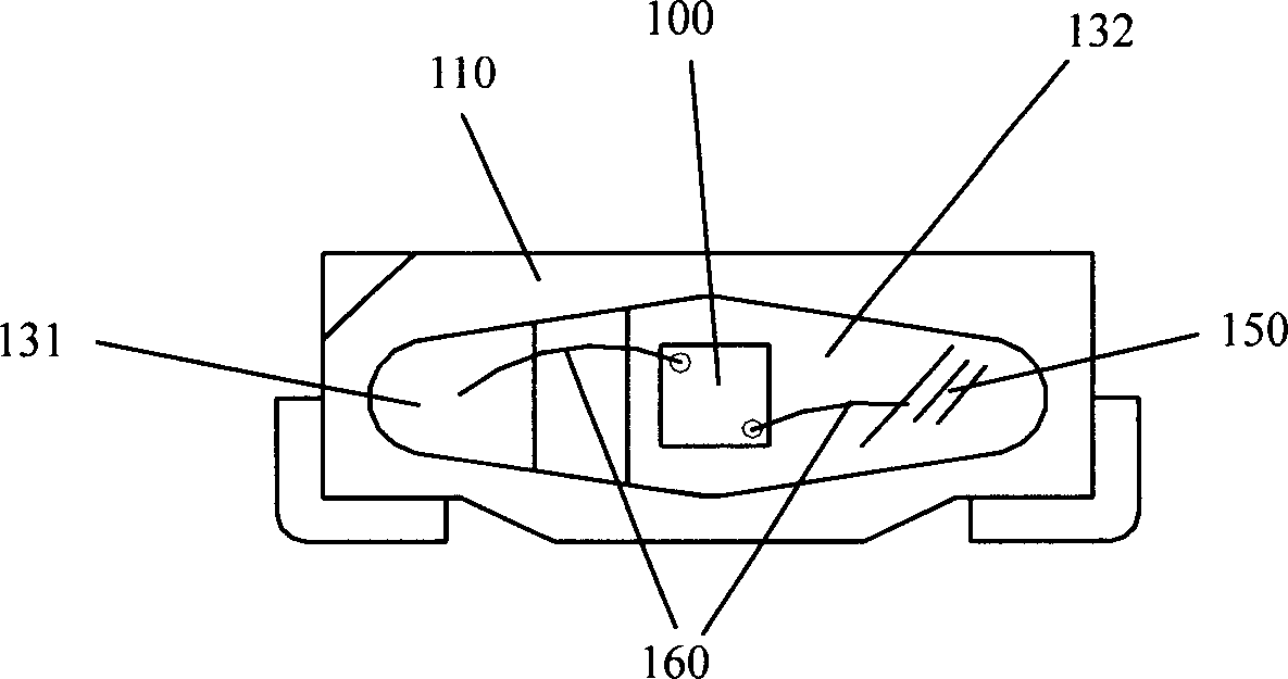
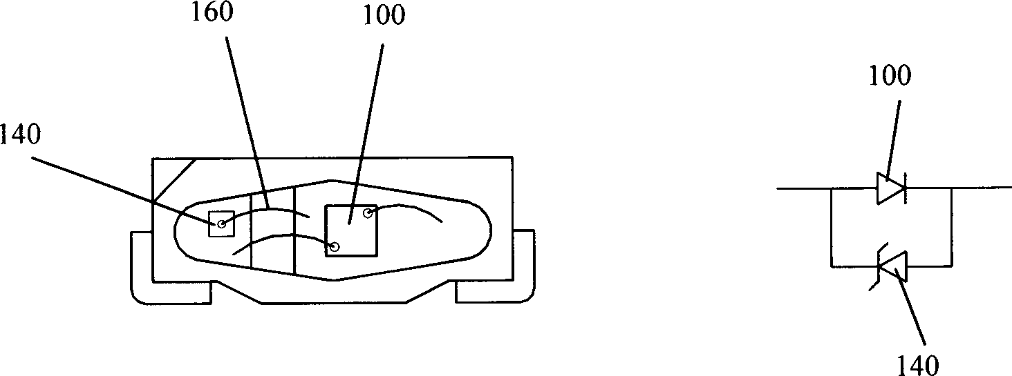
[0025] Figure 5 for in figure 1 and image 3 A technical improvement of the light-emitting diode device shown. Such as Figure 5 As shown, a blue light-emitting diode chip 100 is fixed on a metal lead frame, and the metal lead frame has a reflector 110 and a solid crystal area formed by plastic, and the positive electrode of the chip is connected to the metal lead frame by welding with gold wire or aluminum wire 160. The positive electrode 131 of the chip is connected, and the negative electrode of the chip is connected with the negative electrode 132 of the metal lead frame in the same way. A P-type Zener diode chip 141 is fixed with silver glue on the positive metal lead frame, and its breakdown voltage is 6V; another P-type Zener diode chip 142 is also fixed with silver glue on the negative metal lead frame, and its breakdown voltage is The voltage is 12V. The bonding pads of the two P-type Zener diode chips are connected by gold wire or aluminum wire 160, and the pla...
Embodiment 2
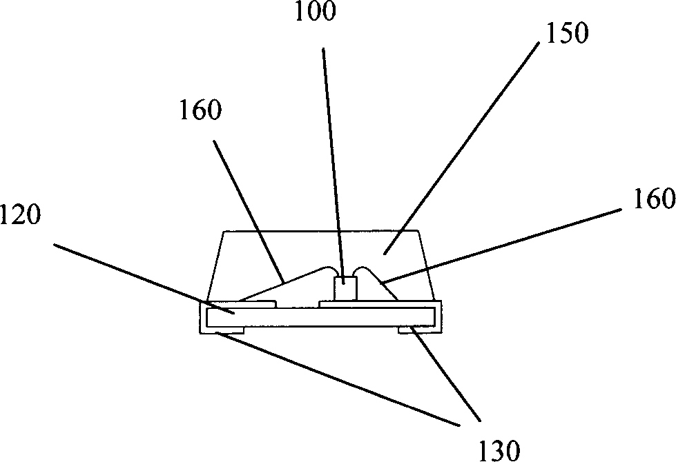
[0028] Such as Figure 7 As shown, a metal lead frame containing positive lead 131 and negative lead 132 is covered with plastic shell 115, and a die-bonding area and a wiring area are exposed, and a light-emitting diode chip 100 is fixed on a printed circuit board in a flip-chip manner. On the carrier 170 of a ceramic material circuit board, a silicon substrate, or a combination thereof, the carrier is provided with a circuit to connect the positive and negative electrodes of the chip, and then adhered to a metal heat sink 180 with thermally conductive adhesive, and the metal heat sink is covered by the above-mentioned plastic shell. Covered but the bottom is exposed, the positive pole of the carrier is connected to the positive pole of the metal lead frame by gold wire or aluminum wire 160 welding, and the negative pole of the carrier is connected to the negative pole of the metal lead frame in the same way; Fix another P-type Zener diode chip 141 with silver glue, and its bre...
Embodiment 3
[0031] Such as Figure 9 As shown, a white light-emitting diode device includes a set of positive and negative metal lead frames 130, a heat dissipation conductor 180 formed of copper metal, and a plastic shell 115 covers the two metal lead frame electrodes and heat dissipation conductors to form a die-bonding area. And the bottom of the heat dissipation conductor is exposed outside the plastic shell. A light-emitting diode blue chip 100 is fixed on the heat dissipation conductor, and the positive and negative pads of the blue chip are welded to the positive and negative metal lead frame with gold wire or aluminum wire, and fixed on the heat sink with silver glue at the same time An N-type zener diode 145 with a breakdown voltage of 5 volts and an N-type red light-emitting diode 146 are connected to the pad of the red light-emitting diode chip to the positive metal lead frame by gold wire or aluminum wire welding, and in the same way Connect the bonding pad of the sodium-zene...
PUM
 Abstract
Description
Claims
Application Information