Steering apparatus

a technology of steering apparatus and steering column, which is applied in the direction of steering column, steering parts, vehicle components, etc., can solve problems such as variations in impact absorption load, and achieve the effect of stable impact absorption load

Active Publication Date: 2018-08-21
JTEKT CORP +1
View PDF9 Cites 3 Cited by
  • Summary
  • Abstract
  • Description
  • Claims
  • Application Information

AI Technical Summary

Benefits of technology

[0005]However, the large-diameter portion 101 of the one end 100a of the support shaft 100 is only partially supported by the lower jacket 110 in the support shaft direction K, and the lower jacket 110 is separated from the first to-be-broken portion H1 only by a predetermined distance D in the support shaft direction K. This is to restrain the locking member 120 from interfering with the lower jacket 110 at the time when the support shaft 100 is broken at the time of a secondary collision.
[0006]The first to-be-broken portion H1 separated from the lower jacket 110 in the support shaft direction K may receive a bending stress at the time of a secondary collision, so as to be broken by bending, not by shearing. The first to-be-broken portion H1 broken by bending and the second to-be-broken portion H2 broken by shearing cannot achieve simultaneous breakage. This may cause variations in impact absorption load. The present disclosure provides a steering apparatus that can obtain a stable impact absorption load.
[0008]In the above aspect, since the first to-be-broken portion is provided in the smallest-diameter portion of the tapered portion adjacent to the stepped portion and having a diameter gradually decreasing toward the stepped portion, a stress concentrates on the first to-be-broken portion. On this account, the first to-be-broken portion is broken by shearing, so that the first to-be-broken portion and the second to-be-broken portion are broken by shearing at the same time. This makes it possible to obtain a stable impact absorption load.

Problems solved by technology

This may cause variations in impact absorption load.

Method used


Image

  • Steering apparatus
  • Steering apparatus
  • Steering apparatus

Examples


Embodiment Construction

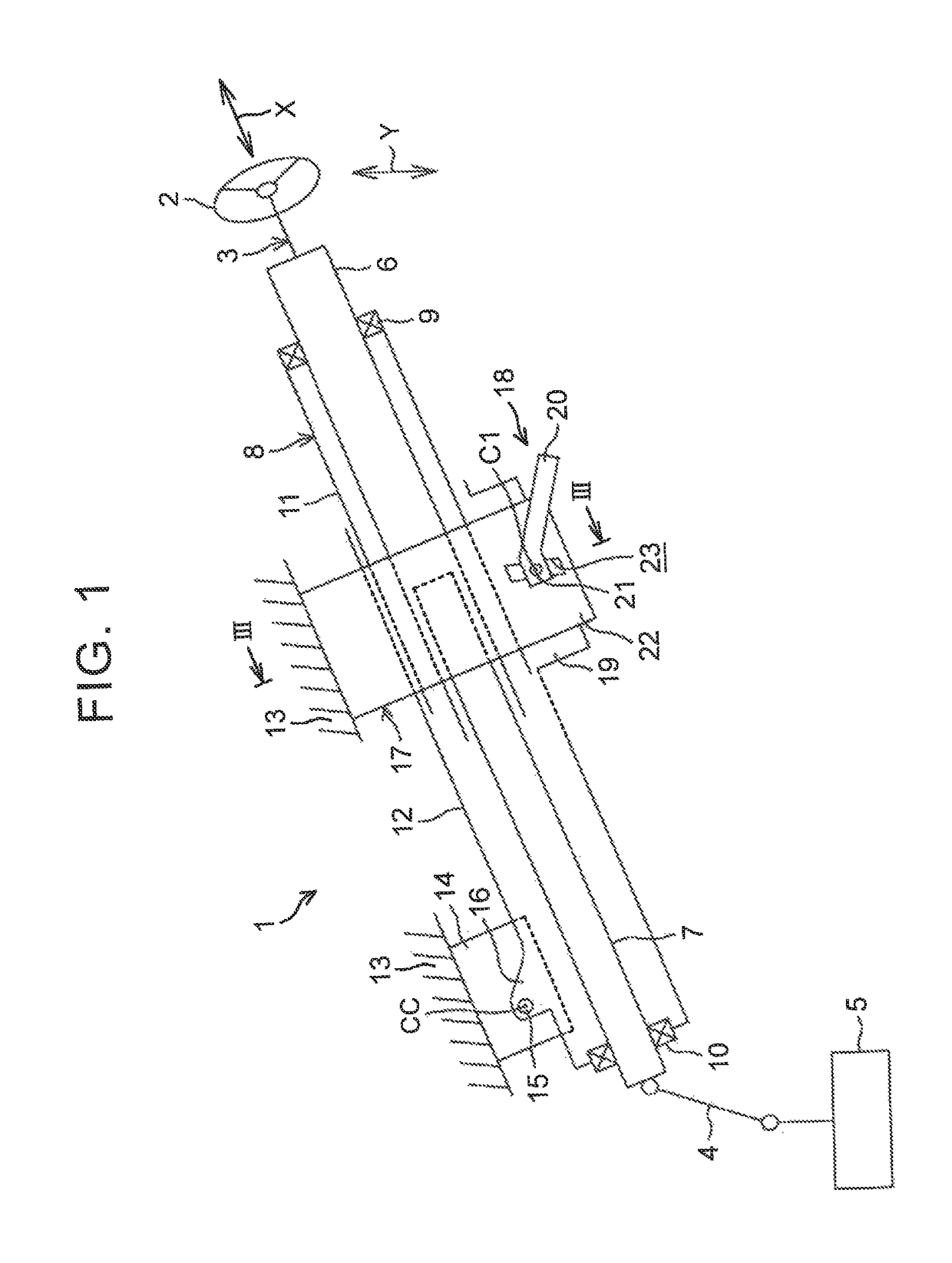
[0020]An embodiment that embodies the present disclosure is described below with reference to the drawings. (First Embodiment) FIG. 1 is a partially breaking schematic side view illustrating a schematic configuration of a steering apparatus according to the first embodiment of the present disclosure. Referring now to FIG. 1, the steering apparatus 1 includes: a steering shaft 3 having one end (an axially upper end) to which a steering member 2 such as a steering wheel is connected; and a steering operation mechanism 5 connected to the steering shaft 3 via an intermediate shaft 4 or the like.

[0021]The steering operation mechanism 5 is, for example, a rack-and-pinion mechanism that steers steered wheels (not shown) in association with steerage of the steering member 2. A rotation of the steering member 2 is transmitted to the steering operation mechanism 5 via the steering shaft 3, the intermediate shaft 4, and so on. Further, the rotation transmitted to the steering operation mechani...


PUM


Abstract

A support shaft includes a first supported portion and a second supported portion supported by respective support holes of a pair of fastened portions. The support shaft includes a large-diameter portion including the first supported portion, a small-diameter portion including the second supported portion and having a diameter smaller than the large-diameter portion, and a stepped portion formed between the large-diameter portion and the small-diameter portion. The small-diameter portion includes a tapered portion provided in the small-diameter portion so as to be adjacent to the stepped portion and having a diameter gradually decreasing toward the stepped portion, a first to-be-broken portion placed in a smallest-diameter portion of the tapered portion so as to be broken at a time of a secondary collision, and a second to-be-broken portion placed adjacent to the second supported portion so as to be broken at the time of the secondary collision.

Description

INCORPORATION BY REFERENCE[0001]The disclosure of Japanese Patent Application No. 2016-077457 filed on Apr. 7, 2016 including the specification, drawings and abstract is incorporated herein by reference in its entirety.BACKGROUND1. Technical Field[0002]The present disclosure relates to a steering apparatus.2. Description of Related Art[0003]As illustrated in FIG. 8, in Japanese Patent Application Publication No. 2015-182614 (JP 2015-182614 A), a locking member 120 rotatably supported by a lower jacket 110 via a support shaft 100 is engaged with a lock plate 130 supported by an upper jacket (not shown), thereby increasing the retentivity of a telescopic lock. The support shaft 100 includes: a large-diameter portion 101 placed in one end 100a thereof in a support shaft direction K; and a small-diameter portion 103 extending from the large-diameter portion 101 toward the other-end-100b side in the support shaft direction K via a stepped portion 102. The support shaft 100 is supported b...

Claims


Application Information

Patent Timeline
Patent Type & Authority Patents(United States)
IPC IPC(8): B62D1/19B62D1/184B62D1/189
CPCB62D1/195B62D1/189B62D1/184B62D1/192
Inventor SAKUDA, MASAYOSHISUGIURA, TOMONORIKUBOTA, TATSUROISHIMURA, SHOJIHOSHINO, SHIGERU
Owner JTEKT CORP
Why Eureka
Try Eureka