Strain reduction clamshell heat exchanger design

a heat exchanger and strain reduction technology, applied in the field of strain reduction clamshell heat exchanger design, gas furnace, etc., can solve the problems of cracking problems, failure of heating chambers, and hot spots at certain points

Active Publication Date: 2018-11-13
LENNOX IND
View PDF19 Cites 0 Cited by
  • Summary
  • Abstract
  • Description
  • Claims
  • Application Information

AI Technical Summary

Problems solved by technology

These 80% furnaces are also characterized by high operating temperatures, which can cause failure within the heating chamber.
As a result, hot spots can occur at certain points in the passageway of the clam shell heat exchanger.
The high operating temperatures that create these hot spots can create cracking problems, often referred to as “hot cracks” in the clamshell heat exchanger panels.
When such cracks appear, their occurrence is considered a failure of the system.

Method used


Image

  • Strain reduction clamshell heat exchanger design
  • Strain reduction clamshell heat exchanger design
  • Strain reduction clamshell heat exchanger design

Examples


Embodiment Construction

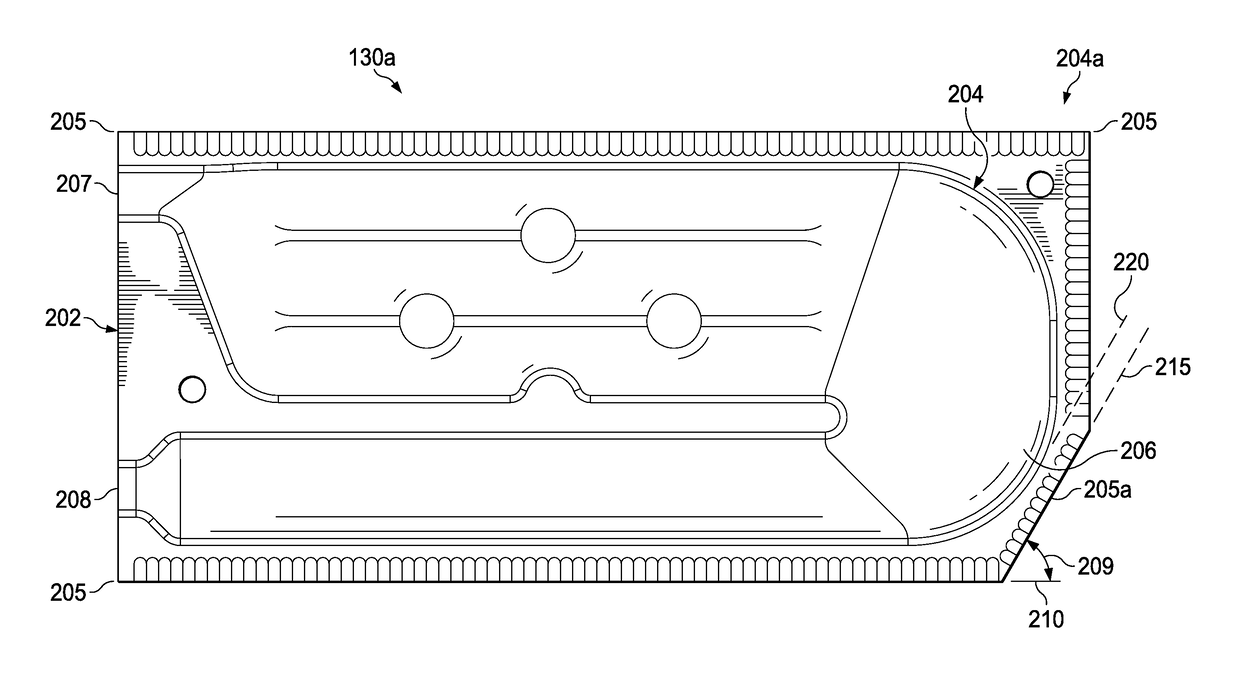
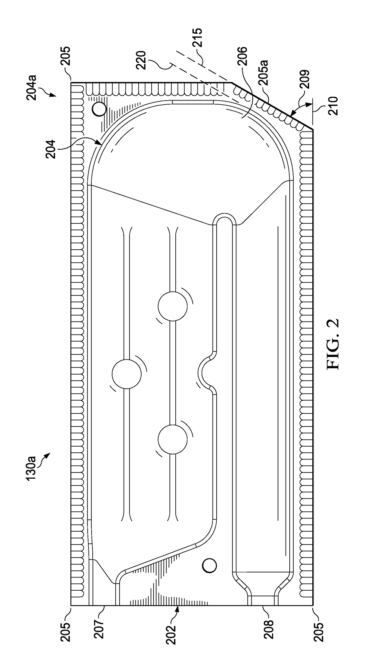
[0011]Described herein are various embodiments of an improved clamshell heating chamber that can be employed in a gas furnace. The present disclosure is based on the discovery that failures typically not only occur in the form of cracks in hot spots (e.g., temperatures of about 1000 degrees), which are known as “hot cracks,” but failure also occurs near relatively cooler spots (e.g. temperatures of about 600 degrees), which are known as “cold cracks” and are the result of high plastic strain within the clamshell panel. The plastic strain is an important variable to the thermal loading, which causes fatigue and cracking failure. The present disclosure recognizes that the plastic strain can be reduced by modifying the existing clamshells by truncating the corner adjacent a cold crack region. Cold crack regions are of particular concern because the hot crack regions can be addressed with baffling or other known solutions that work in view of the higher operating temperatures in that re...


PUM


Abstract

One aspect of this disclosure provides a heating chamber for a gas furnace that comprises opposing halves joined together. The joined opposing halves form a clamshell panel having at least one truncated corner located adjacent a curve located at a back end of a chamber path of the one or more clamshell heating chambers.

Description

TECHNICAL FIELD[0001]This application is directed, in general, to heating, ventilation and air conditioning (HVAC) systems and, more specifically, to a gas furnace that comprises a clamshell heat exchanger having reduced plastic strain.BACKGROUND[0002]A conventional gas furnace typically employs several heat exchangers, which form a heating zone to warm an air stream passing through the furnace. An 80% furnace is one where approximately 80% of the energy put into the furnace is converted into heat for the purposes of heating the targeted space. These 80% furnaces include “clamshell” or individual panel halves typically formed by stamping mirror images of the combustion chambers into corresponding metal sheets and coupling them together. The air passes through the heating zone from a blower or fan. These 80% furnaces are also characterized by high operating temperatures, which can cause failure within the heating chamber. As a result, hot spots can occur at certain points in the pass...

Claims


Application Information

Patent Timeline
Patent Type & Authority Patents(United States)
IPC IPC(8): F24H3/10F28F3/12F28D9/00F24D5/00F24H9/00
CPCF24D5/00F28F3/12F24H9/0068F28D9/0031F24H9/0063F24H3/105
Inventor NOMAN, SHIBLEE S. M.WHITESITT, JOHN W.
Owner LENNOX IND
Why Eureka
Try Eureka