Lens and light source apparatus

a technology of light source and lens, applied in the direction of lighting and heating apparatus, semiconductor devices for light sources, instruments, etc., can solve the problems of affecting the image quality of the display, affecting the uniformity of illumination within the effective illumination region, etc., to achieve better uniformity of light energy distribution, increase the emitting angle, and large light divergent angle

Inactive Publication Date: 2018-11-20
CAL COMP ELECTRONICS +1
View PDF5 Cites 1 Cited by
  • Summary
  • Abstract
  • Description
  • Claims
  • Application Information

AI Technical Summary

Benefits of technology

[0008]The invention provides a lens, which can increase the divergent angle of the light source.
[0021]As to the foregoing descriptions, the light source apparatus of the embodiments in the invention can increase the emitting angle at the side of the light source apparatus based on the configuration of the cavity region in the lens and then has large light divergent angle. A better uniformity for the distribution of light energy as a whole can be achieved.

Problems solved by technology

When the LED light source is applied to the backlight module, the luminance uniformity within the effective illumination region would be affected, and the image quality of the display would be then affected.

Method used


Image

  • Lens and light source apparatus
  • Lens and light source apparatus
  • Lens and light source apparatus

Examples


Embodiment Construction

[0027]Reference will now be made in detail to the present preferred embodiments of the invention, examples of which are illustrated in the accompanying drawings. Wherever possible, the same reference numbers are used in the drawings and the description to refer to the same or like parts.

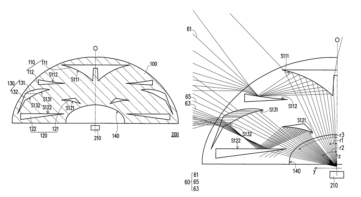
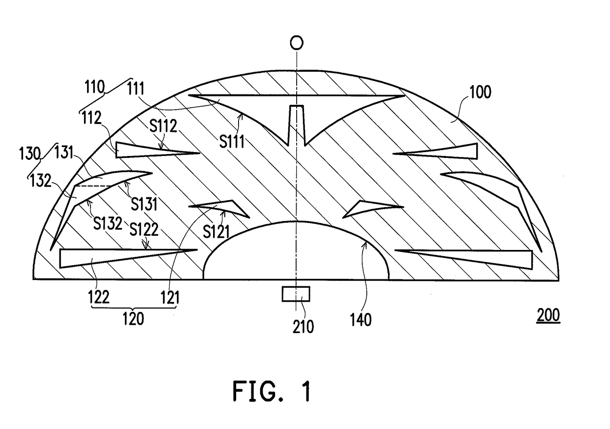
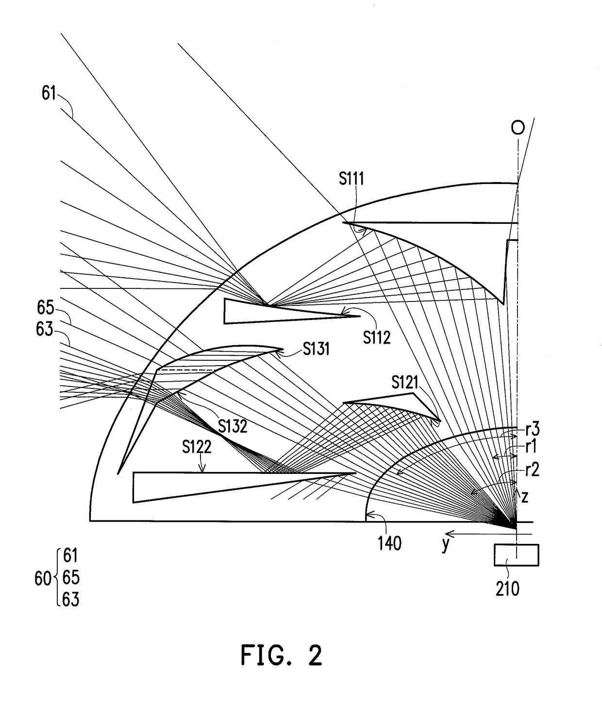
[0028]FIG. 1 is a drawing, schematically illustrating the structure of a light source apparatus, according to an embodiment of the invention. FIG. 2 is a drawing, schematically illustrating the light path of the light source apparatus in FIG. 1, according to an embodiment of the invention. Referring to FIG. 1, in an embodiment, the light source apparatus 200 comprises a lens 100 and a light emitting device 210. In addition, the shape of the lens 100 in an embodiment can be hemispherical as an example. The material of the lens 100 can be polycarbonate (PC), as an example, which can be fabricated by a fabrication method, such as the three dimensional printing method. The light emitting device 210 can b...


PUM


Abstract

A lens including a first set of cavity regions, a second set of cavity regions and a third set of cavity regions is provided. The first set of cavity regions includes a first cavity region and a second cavity region, and a first reflection curved surface of the first cavity region faces a second reflection curved surface of the second cavity region. The second set of cavity regions includes a third cavity region and a fourth cavity region, and a third reflection curved surface of the third cavity region faces a first reflecting plane of the fourth cavity region. The third set of cavity regions includes a fifth cavity region and a sixth cavity region, and the first reflecting plane faces a refraction curved surface of the fifth cavity region and a refraction plane of the sixth cavity region. A light source apparatus is also provided.

Description

CROSS-REFERENCE TO RELATED APPLICATION[0001]This application claims the priority benefit of Taiwan application serial no. 104143557, filed on Dec. 24, 2015. The entirety of the above-mentioned patent application is hereby incorporated by reference herein and made a part of this specification.BACKGROUND OF THE INVENTION[0002]1. Field of the Invention[0003]The present invention generally relates to optical device and optical apparatus, in particular, to a lens and a light source apparatus.[0004]2. Description of Related Art[0005]As the development in optical technology, more and more the light shapes of light source apparatus for providing illumination has been developed. For the light emitting device in the light source apparatus, such as light emitting die or filament, the variations of the illuminating light shape as provided are relatively few. To provide more probabilities for the light shape, the technology for the lens with various proper shapes and configured on the light path...

Claims


Application Information

Patent Timeline
Patent Type & Authority Patents(United States)
IPC IPC(8): F21V5/04G02B13/00F21V7/00F21Y115/10
CPCG02B13/00F21Y2115/10F21V7/0091F21V5/04G02B19/0028G02B19/0071
Inventor WANG, CHUN-MIN
Owner CAL COMP ELECTRONICS
Why Eureka
Try Eureka