Cylindrical battery

a safety mechanism and battery technology, applied in the direction of batteries, cell components, cell component details, etc., can solve the problem of increasing the pressure of gas

Active Publication Date: 2019-02-19
FDK CORP
View PDF7 Cites 0 Cited by
  • Summary
  • Abstract
  • Description
  • Claims
  • Application Information

AI Technical Summary

Benefits of technology

[0012]The present disclosure has been made from such view points, and an object thereof is to provide a cylindrical battery excellent in safety and productivity.

Problems solved by technology

Therefore, when a large amount of gas is generated inside the battery for some reason, releasing of the gas may be too late, which may increase the pressure of the gas, to detach the washer 50.

Method used


Image

  • Cylindrical battery
  • Cylindrical battery
  • Cylindrical battery

Examples


Embodiment Construction

[0047]At least the following details will become apparent from descriptions of the present specification and of the accompanying drawings.

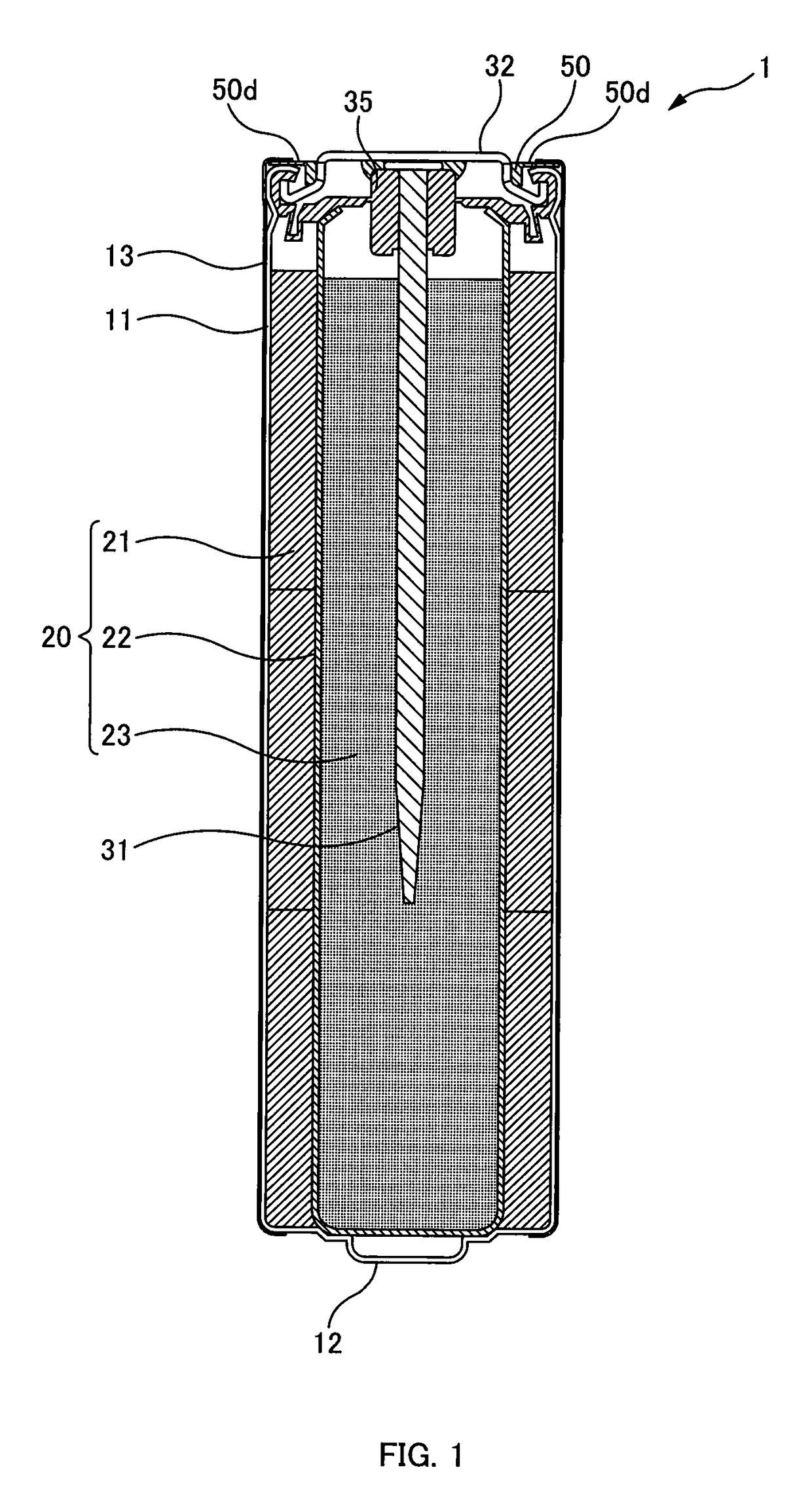
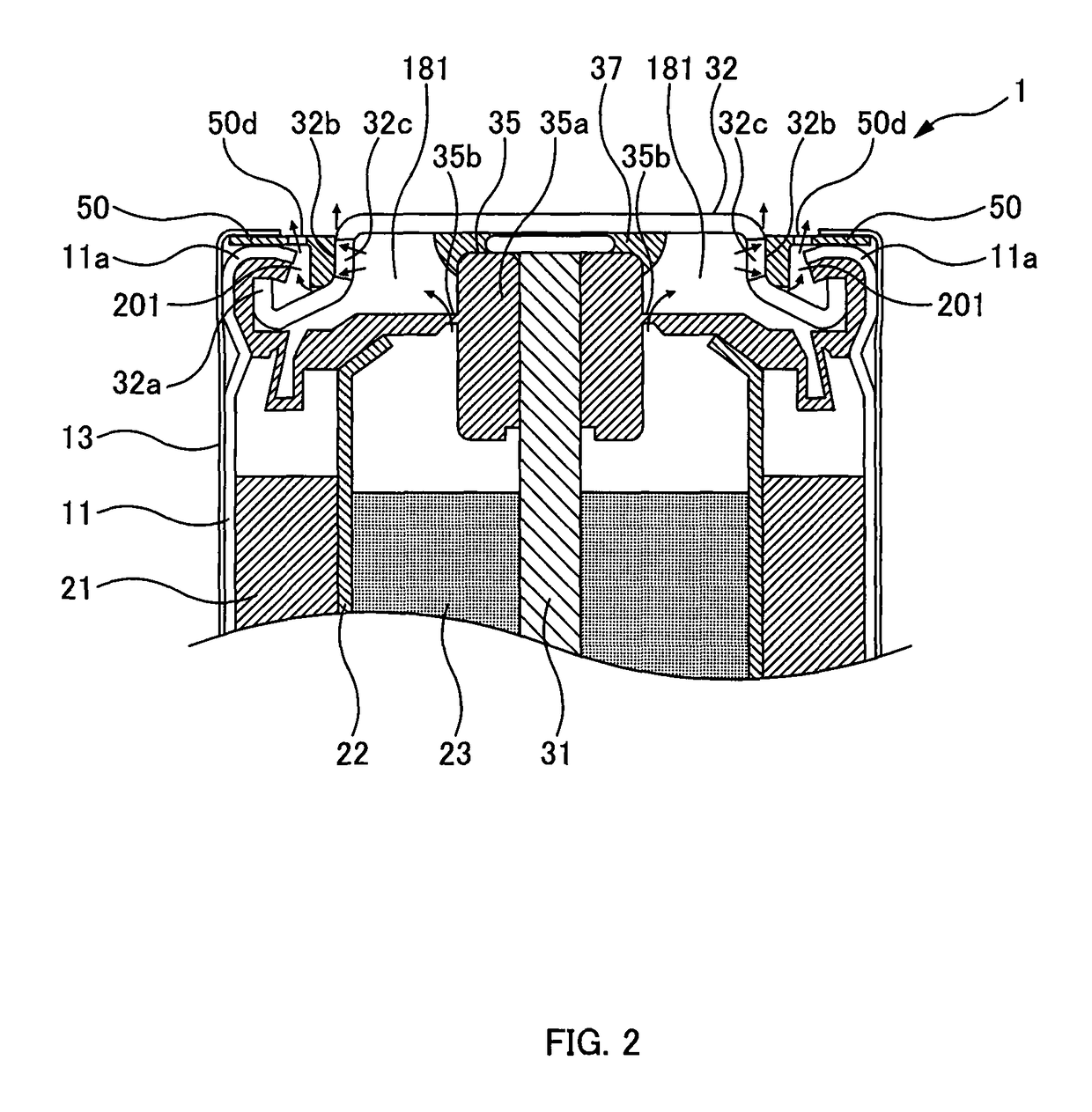
[0048]FIG. 1 illustrates a structure of a cylindrical alkaline battery (alkaline battery of type LR6 (AA)) (hereinafter, referred to as an alkaline battery 1) as an example of a cylindrical battery of the present disclosure. The drawing is a longitudinal sectional view illustrating the alkaline battery 1 (sectional view when a direction extending the cylindrical axis of the alkaline battery 1 is defined as an up-down (longitudinal) direction). FIG. 2 is an enlarged partial cross-sectional view illustrating an anode side and therearound of the alkaline battery 1 in FIG. 1.

[0049]As illustrated in these drawings, the alkaline battery 1 includes: a metal cathode can 11 (battery can) in a bottomed cylindrical shape; a cathode mixture 21 inserted in the cathode can 11; a bottomed cylindrical separator 22 provided on the inner peripheral side of the cath...


PUM

PropertyMeasurementUnit
insulating propertiesaaaaaaaaaa
areaaaaaaaaaaa
structureaaaaaaaaaa

Abstract

In a cylindrical battery including a gap formed between a peripheral side surface 32b of a dish-shaped portion in an anode terminal plate 32 and a curved end portion 11a of a cathode can 11, and a washer 50 having a cylindrical boss portion 50a and an annular flange portion 50c provided around an upper end surface of the cylindrical boss portion 50athe washer 50 being mounted to an opening portion of a cathode can 11 such that the cylindrical boss portion 50a is fitted into the gap 201, a vent structure configured to release gas released to the gap 201 from a first vent hole 32c in the anode terminal plate 32 to an exterior of the cylindrical battery (1) from an arc-shaped second vent hole (50d) formed in the flange portion(50c) or an annular gap (301, 302) formed between the upper end surface of the cylindrical boss portion (50a) and the terminal plate(32).

Description

CROSS-REFERENCE TO RELATED APPLICATION[0001]This application claims the benefit of priority to Japanese Patent Application No. 2015-073854, filed Mar. 31, 2015, of which full contents are incorporated herein by reference.BACKGROUND OF THE INVENTION[0002]Field of the Invention[0003]The present invention relates to a safety mechanism of a cylindrical battery.[0004]Description of the Related Art[0005]FIGS. 17 to 20 illustrate a structure of an alkaline battery 100 (cylindrical alkaline battery of type LR6). In these drawings, FIG. 17 is a longitudinal sectional view illustrating the alkaline battery 100 when a direction extending the cylindrical axis of the alkaline battery 100 is defined as a longitudinal direction, and FIG. 18 is an enlarged view illustrating an anode terminal plate and therearound of the alkaline battery 100 in FIG. 17.[0006]As illustrated in FIG. 17, the alkaline battery 100 includes: a metal cathode can 11 in a bottomed cylindrical shape; a cathode mixture 21 in a...

Claims


Application Information

Patent Timeline
Patent Type & Authority Patents(United States)
IPC IPC(8): H01M2/12H01M2/34H01M2/02H01M2/04H01M6/06H01M50/167H01M50/367H01M50/548H01M50/559H01M50/586H01M50/593
CPCH01M2/1235H01M2/022H01M2/0413H01M2/34H01M2/1252H01M2200/00H01M6/06H01M6/08H01M2200/30H01M50/394H01M50/597H01M50/586H01M50/367H01M50/593H01M50/167H01M50/548H01M50/559H01M50/107H01M50/171H01M50/342
Inventor YAMAZAKI, TATSUYAKUNIYA, SHIGEYUKI
Owner FDK CORP
Why Eureka
Try Eureka