Water heating system

a water heating system and water heater technology, applied in the direction of combustion control, failure to operate, heating types, etc., can solve the problems of compromising the superiority of the linked water heating system, the inability of the water heating system to supply hot water at all, and the inability to operate the remaining normal water heater

Active Publication Date: 2019-03-26
NORITZ CORP
View PDF10 Cites 1 Cited by
  • Summary
  • Abstract
  • Description
  • Claims
  • Application Information

AI Technical Summary

Benefits of technology

[0007]This invention was made to solve such problems, and an object of this invention is to provide a water heating system which can continue an operation as long as possible even when an abnormal condition occurs in at least one of a plurality of linked water heaters.

Problems solved by technology

Therefore, when an abnormal condition which may interfere the operation of the fan occurs in any water heater of the plurality of water heaters, the exhaust from the exhaust duct assembly may flow back into the abnormal water heater.
When the total stop is set, however, remaining normal water heaters can no longer operate and the water heating system is unable to supply hot water at all.
Consequently, superiority of the linked water heating system may be compromised and convenience of a user may also be compromised.

Method used


Image

  • Water heating system
  • Water heating system
  • Water heating system

Examples


first embodiment

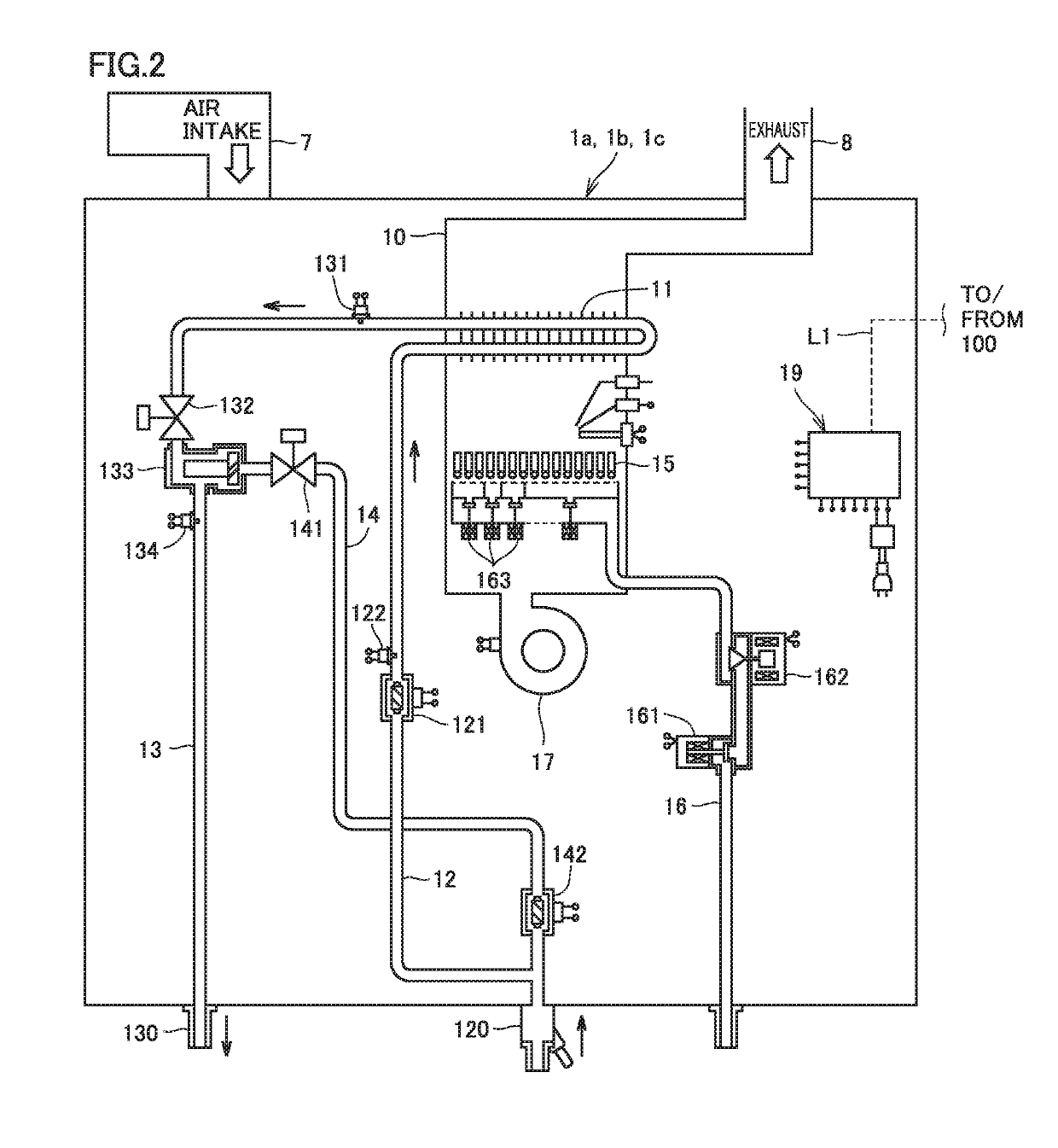
[0018]A water heating system implemented by linking three water heaters in parallel will initially be described in a first embodiment of the present invention. Though a latent heat recovery type water heater which can recover latent heat of a combustion gas is described as each water heater of a water heating system 110 according to the present first embodiment, a type of heating by the water heater is not limited to the latent heat recovery type. The number of water heaters implementing water heating system 110 is not limited to three and two or four or more water heaters are applicable.

Configuration of Water Heating System

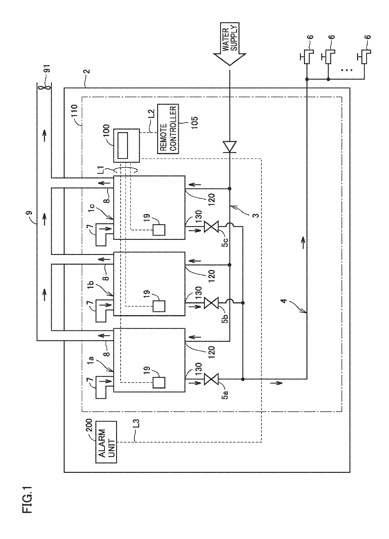
[0019]FIG. 1 is a diagram showing an overall configuration of water heating system 110 according to the first embodiment of the present invention. Water heating system 110 according to the first embodiment is installed in the inside of a room 2.

[0020]Referring to FIG. 1, water heating system 110 includes water heaters 1a, 1b, and 1c, a water supply pipe 3 for sup...

second embodiment

[0090]A simplified two-unit-linked water heating system in which two water heaters are linked in parallel will be described in a second embodiment of the present invention.

Configuration of Water Heating System

[0091]FIG. 5 is a diagram showing an overall configuration of a water heating system 111 according to the second embodiment. In water heating system 111 according to the second embodiment, hot water supply control unit 19 of one water heater 1 also serves as controller 100 which collectively controls two water heaters 1.

[0092]An overall configuration of water heating system 111 according to the second embodiment will initially be described mainly with reference to a difference from water heating system 110 according to the first embodiment.

[0093]Referring to FIG. 5, water heating system 111 includes two water heaters 1d and 1e and is installed in room 2.

[0094]A hot water supply control unit 19d of water heater 1d and a hot water supply control unit 19e of water heater 1e are co...


PUM


Abstract

A controller is configured to set total stop in which operations of all of a plurality of water heaters are stopped when an abnormal condition of a fan or an abnormal condition in communication is sensed in any of the plurality of water heaters while at least one of the plurality of water heaters is operating. The controller is further configured not to set total stop when an abnormal condition of the fan or an abnormal condition in communication is sensed in at least one of the plurality of water heaters while a sensing element for sensing a backflow of an exhaust from an exhaust path assembly is connected to the controller.

Description

BACKGROUND OF THE INVENTIONField of the Invention[0001]This invention relates to a water heating system and more particularly to a water heating system in which a plurality of water heaters are linked to one another.Description of the Background Art[0002]A water heating system in which a plurality of water heaters are linked in parallel (which is hereinafter also referred to as a linked water heating system) has been known. In such a water heating system, hot water can be supplied at a high flow rate by connecting a hot water supply control unit of each water heater to a controller and collectively controlling all water heaters in accordance with a control signal from the controller to each hot water supply control unit.[0003]For example, Japanese Patent Laying-Open No. 2016-121851 shows what is called a common vent type linked water heating system configured to connect an exhaust duct of each water heater to a common exhaust duct assembly and to collect a combustion exhaust generat...

Claims


Application Information

Patent Timeline
Patent Type & Authority Patents(United States)
IPC IPC(8): F24H9/20F23N5/24F23J11/12F23C6/02F24D12/02
CPCF24H9/2042F23C6/02F23J11/12F23N5/242F24D12/02F23N2041/04F23J2211/20F23N2031/28F23N2037/02F23N2231/28F23N2237/02F23N2241/04Y02B30/00F24H15/238F24H15/281F24H15/365F24H15/215F24H15/174F24H15/45F24H15/116F24H15/104F24H15/315F24H15/31F24H15/395F24H15/20F24H15/35F24H15/235F24H15/242F24H15/176
Inventor MUKO, TAKAOOKAMOTO, SHINICHI
Owner NORITZ CORP
Why Eureka
Try Eureka