Non-pneumatic tire

a technology of non-pneumatic tires and rubber tires, which is applied in the direction of agricultural vehicle tires, vehicle components, vehicles, etc., can solve the problems of slowing or temporarily stopping irrigation operations, rubber tires are subject to wear and tear,

Inactive Publication Date: 2019-05-07
RAULERSON JR JAMES MARKLEE +1
View PDF20 Cites 5 Cited by
  • Summary
  • Abstract
  • Description
  • Claims
  • Application Information

AI Technical Summary

Problems solved by technology

Rubber tires are subject to wear and tear and can suffer flats, which in turn requires that the flat be repaired or the tire be replaced entirely.
The weight of the irrigation system can cause the tires to sink and get stuck as they move through a muddy field, which can slow or temporarily halt irrigation operations.

Method used


Image

  • Non-pneumatic tire
  • Non-pneumatic tire
  • Non-pneumatic tire

Examples


Embodiment Construction

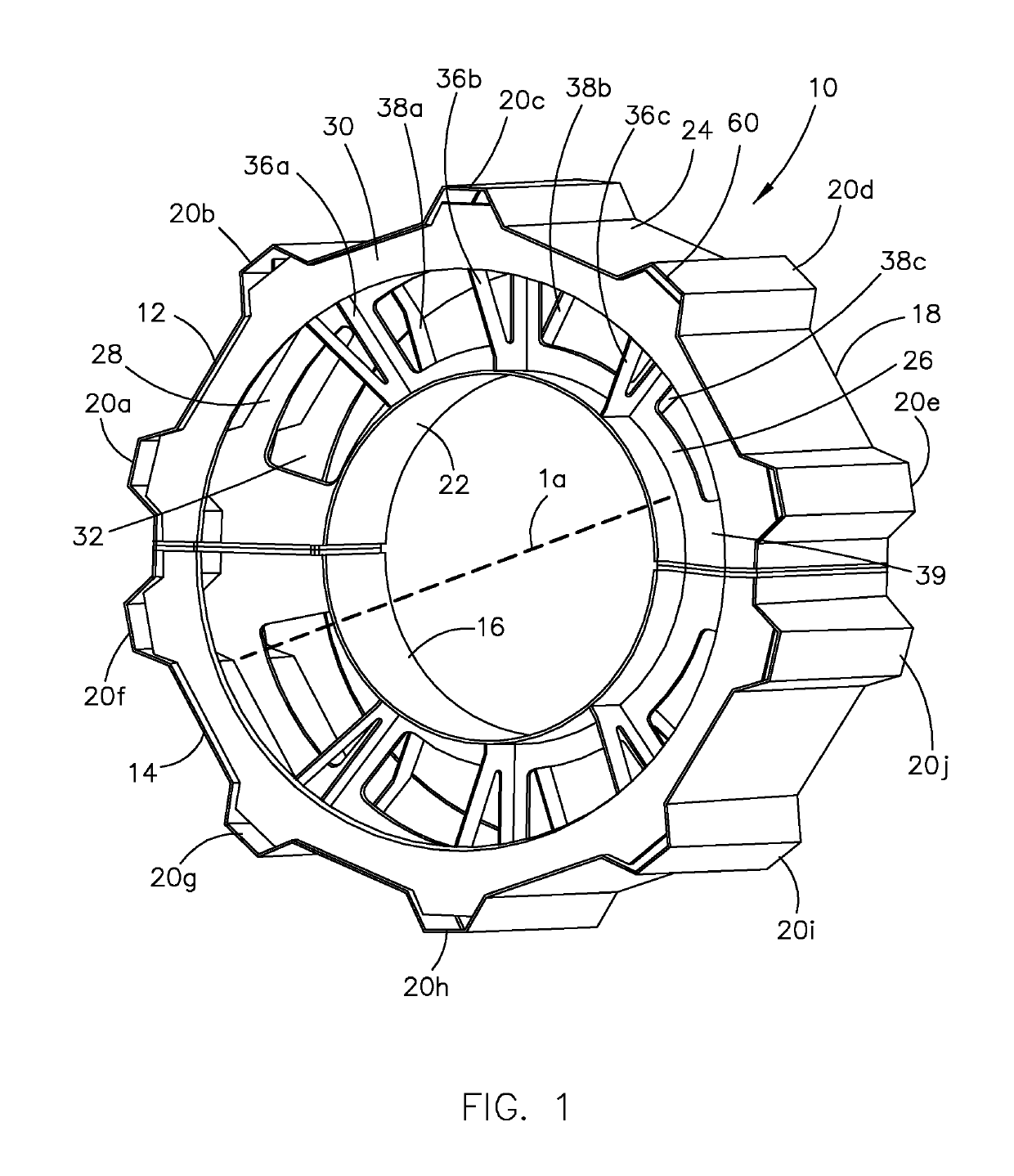
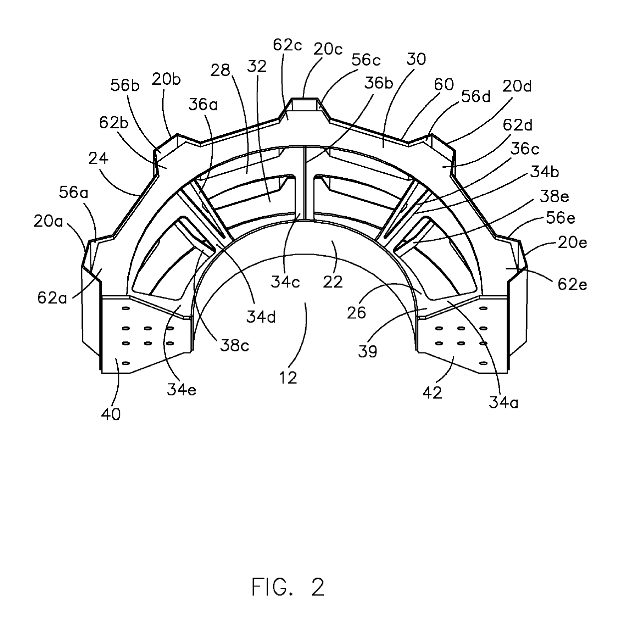
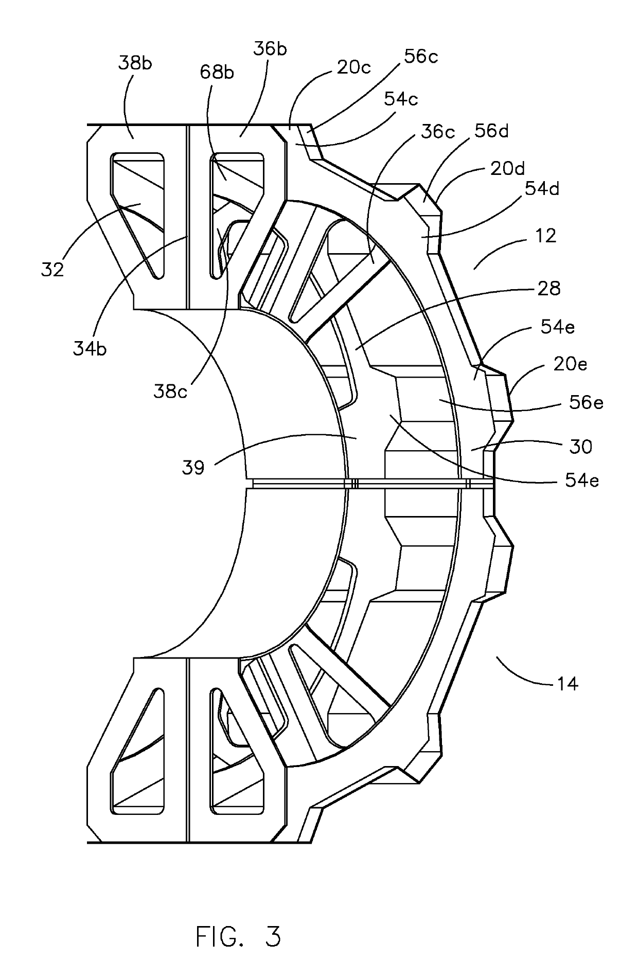
[0022]One exemplary embodiment of a non-pneumatic tire is shown in FIG. 1 and designated with the numeral 10. Non-pneumatic tire 10 is configured to be mounted on a wheel, such as wheel 11 shown in FIG. 6. Non-pneumatic tire 10 and wheel 11 may be used with any suitable device, including a center-pivot irrigation system. Non-pneumatic tire 10 may serve as a replacement for other tires, including conventional inflatable tires designed for use with standard or existing wheels. Non-pneumatic tire 10 is generally cylindrical and is relatively symmetrical about both its central axis 1a and a plane 1b (FIG. 5) that is perpendicular to central axis 1a and aligned with an axial center of the tire 10. Non-pneumatic tire 10 includes an arcuate first tire section 12 and an arcuate second tire section 14 that are joined to define a cylindrical inner wall 16 and a cylindrical outer wall 18 that includes a plurality of traction cleats 20a-j extending radially outward from the remainder of the out...


PUM


Abstract

A non-pneumatic tire having at least two tire sections that are operable to be coupled together. Each tire section includes an inner wall, an outer wall, and a plurality of radial supports that extend from the inner wall to the outer wall such that there is no interior volume enclosed by any combination of the inner wall, the outer wall, and the plurality of radial supports.

Description

CROSS-REFERENCE TO RELATED APPLICATIONS[0001]Not applicable.STATEMENT REGARDING FEDERALLY SPONSORED RESEARCH OR DEVELOPMENT[0002]Not applicable.BACKGROUND OF THE INVENTION[0003]1. Field of the Invention[0004]The present invention is directed toward a non-pneumatic tire that is configured to be mounted on a wheel, including, but not limited to, a wheel for a center-pivot irrigation system.[0005]2. Description of Related Art[0006]Tires are typically made from rubber and must be inflated in order to operate properly. Rubber tires are subject to wear and tear and can suffer flats, which in turn requires that the flat be repaired or the tire be replaced entirely.[0007]In a typical center-pivot irrigation system, water from a centrally located source, such as a well, is directed along a boom pipe to a field. The boom pivots around a center point on spaced apart towers, which support the boom. The towers are usually supported by wheels with large rubber tires. The weight of the irrigation ...

Claims


Application Information

Patent Timeline
Patent Type & Authority Patents(United States)
IPC IPC(8): B60C7/00B60C7/08B60C7/10B60C7/14
CPCB60C7/08B60C2200/08B60C2007/146B60C2007/107B60C7/107B60C7/146
Inventor RAULERSON, JR., JAMES MARKLEERHODES, RILEY
Owner RAULERSON JR JAMES MARKLEE
Why Eureka
Try Eureka