Connector

a technology of connectors and water-repellent structures, which is applied in the direction of couplings/cases, coupling device connections, electrical devices, etc., can solve the problems of inspection process, small positional deviations that are difficult to visually confirm, and cannot achieve the effect of appropriate sealing performance in some cases, etc., and achieve the effect of easy mounting and more smoothly mounting

Active Publication Date: 2019-07-16
SUMITOMO WIRING SYST LTD
View PDF15 Cites 0 Cited by
  • Summary
  • Abstract
  • Description
  • Claims
  • Application Information

AI Technical Summary

Benefits of technology

[0010]Retaining the seal ring prevents a positional deviation of the seal ring during transportation and the like. Thus, a reliable sealing function can be obtained when the retainer is mounted into the housing. Further, proper mounting of the seal ring is assured by visually confirming that the locking head of the retaining portion has passed to the back side of the locking hole and, consequently, it can ensured that a proper sealing function is exhibited when the retainer is mounted. Thus, a large-scale inspection process for inspecting the presence or absence of leakage need not be performed, and a connector assembling process can be simplified.
[0013]Accordingly, the retaining portion is plate-shaped such that the locking head protrudes laterally from both side edges of the retaining portion. Thus, even if the rear edge of the locking head is formed to be at a right angle to the axis line, the retaining portion can be removed forcibly by suppressing an area of engagement with an edge of the mold hole. As a result, a high retaining force can be obtained.
[0015]By forming the cut groove at the position corresponding to the inner side of the lip on the inner peripheral surface of the seal ring, a thickness of the seal ring is substantially constant in an axial direction. The seal ring is mounted slidingly on the outer peripheral surface of the fitting tube while receiving frictional resistance. However, since the thickness of the seal ring is substantially constant as described above, the seal ring will not buckle during mounting and, consequently, the seal ring can be mounted more smoothly.
[0016]The locking head of the retaining portion may have a tapered shape. Thus, the locking head of the retaining portion is pushed easily into the locking hole and, consequently, the seal ring is mounted easily.
[0017]According to this specification, the seal ring can be held firmly at the proper position and whether or not a holding state is appropriate easily can be confirmed visually.

Problems solved by technology

The seal ring is held only by frictional engagement and may be displaced due to vibration during transportation or the like.
If the retainer is mounted into the housing with a positional deviation of the seal ring overlooked, appropriate sealing performance cannot be expected in some cases.
Particularly, a small positional deviation is difficult to confirm visually.
Thus, there has been a problem that an inspection process for inspecting the presence or absence of leakage has to be performed after the mounting of the retainer.
However, the locking head needs to be removed forcibly from a mold hole of a mold.
Thus, there is a limit in making an angle of the rear edge of the locking head closer to a right angle.

Method used


Image

  • Connector
  • Connector
  • Connector

Examples


Embodiment Construction

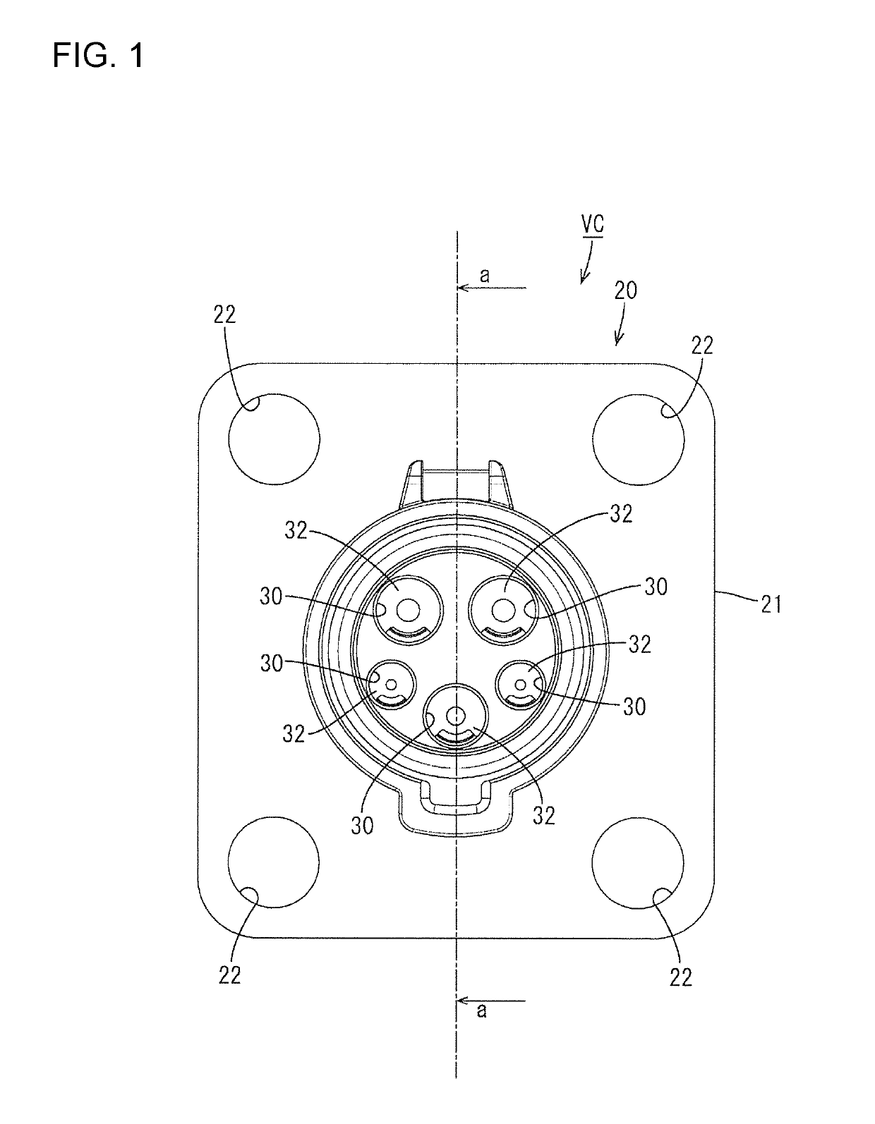
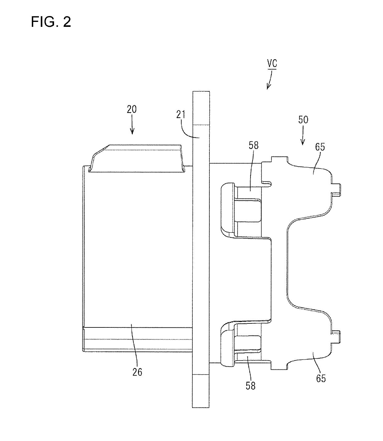
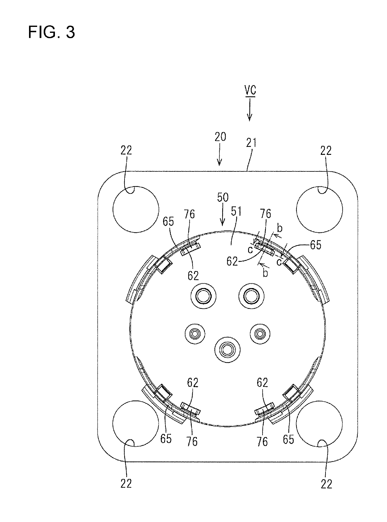
[0037]An embodiment applied to a vehicle-side connector is described with reference to FIGS. 1 to 19. A vehicle-side connector VC of this embodiment is connected to a battery (not shown) mounted in an electric vehicle, a hybrid vehicle or the like and fit and connected to a charging connector (not shown) when charging this battery. The vehicle-side connector VC is a five-pole connector and includes, as shown in FIGS. 1 to 4, an inlet housing 20 (hereinafter, housing 20) accommodating unillustrated terminal fittings and to be mounted on a body of the vehicle, and a retainer 50 to be mounted on a rear surface side of the housing 20 to retain the terminal fittings.

[0038]Although not shown, the terminal fittings include two power terminals, one ground terminal and two signal terminals, and have a similar basic structure although diameters and the like may be different depending on types. The terminal fittings are described below, taking the ground terminal as an example.

[0039]The termin...


PUM


Abstract

A connector includes a housing (20) with a terminal accommodation chamber (30). A retainer (50) covers a rear opening (40A) of the housing (20), and a fitting tube (53) on a front surface of the retainer (50) is fit into the rear opening (40A) of the housing (20). A seal ring (70) is mounted on an outer peripheral surface of the fitting tube (53) and is compressed between the outer peripheral surface of the fitting tube (53) and an inner peripheral surface of the rear surface opening (40A). A retaining portion (75) having a locking head (76) on a tip projects on a rear surface of the seal ring (70). A locking hole (62) is provided in a periphery of the retainer (50), the retaining portion (75) being passable through the locking hole, and the locking head (76) is locked to an edge of the locking hole (62) from behind.

Description

BACKGROUND[0001]Field of the Invention[0002]This specification relates to a waterproof structure in a connector, such as a vehicle-side connector applied for charging.[0003]Related Art[0004]Japanese Unexamined Patent Publication No. 2011-24903 discloses a vehicle-side connector to be connected to a charging connector during charging. This connector includes a terminal fitting having a wire connecting portion connected to an end of a wire, a housing provided with a terminal accommodation chamber into which the terminal fitting is to be inserted from behind, and a retainer to retain the terminal fitting by being mounted to cover a rear opening of the housing.[0005]The vehicle-side connector of this type requires waterproofing measures to be taken for a part of the housing where the retainer is mounted. A relatively simple waterproof structure provides a fitting tube on the front surface of the retainer. The fitting tube can fit into the rear opening of the housing with a clearance. A ...

Claims


Application Information

Patent Timeline
Patent Type & Authority Patents(United States)
IPC IPC(8): H01R13/52H01R13/436
CPCH01R13/5202H01R13/4367H01R13/506
Inventor TAKAHASHI, KENYA
Owner SUMITOMO WIRING SYST LTD
Why Eureka
Try Eureka