Lid seal for cylindrical containers

A technology for sealing cylindrical cans and caps, which is applied to bottle/container caps, capping containers with caps, applications, etc. It can solve problems such as damage to the sealing machine, achieve reliable sealing effects, reduce production costs, and reliable sealing performance Effect

Inactive Publication Date: 2006-08-09
YAMATO IRON WORKS CO LTD
View PDF1 Cites 0 Cited by
  • Summary
  • Abstract
  • Description
  • Claims
  • Application Information

AI Technical Summary

Problems solved by technology

Furthermore, when the lid seal is fitted on the fixed mouthpiece of the cylindrical can, if there is such an arc-shaped depression in the lower edge portion of the drooping shape peripheral wall of the lid seal, the drooping shape peripheral wall of the lid seal at the recessed position will A gap is created between the lower edge portion and the top of the cylindrical can, so that a tool such as a screwdriver can be inserted into the gap, and the cap seal can be removed by improper means, so there is a mouth joint of the cylindrical can caused by the cap seal. The problem that the sealing function of the Ministry is damaged

Method used


Image

  • Lid seal for cylindrical containers
  • Lid seal for cylindrical containers
  • Lid seal for cylindrical containers

Examples


no. 1 approach

[0024] In different drawings, the same part is represented by the same symbol.

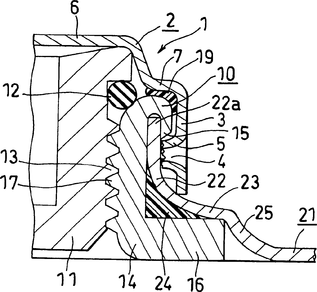
[0025] Figure 1~ Figure 4 It is used to explain the first embodiment of the present invention. In addition, usually on the top (21) of the cylindrical tank, there are two large mouthpieces (10) of different sizes, one large and one small, or the same size, but the one shown in this embodiment is a larger mouthpiece. Department (10).

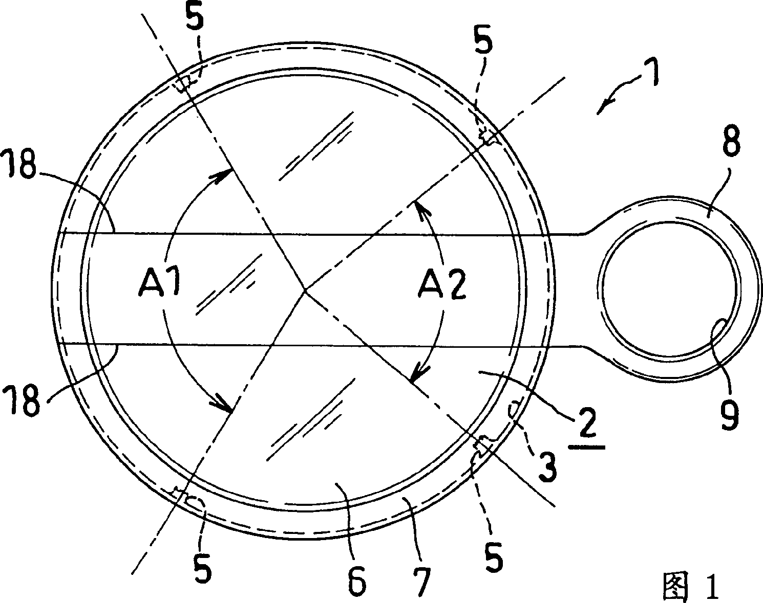
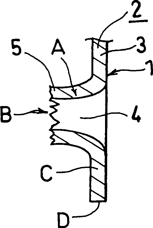
[0026] As shown in Figure 1, according to the present invention, the cover seal (1) is provided with a through hole (4) and a ring-shaped serrated protrusion (5), wherein the through hole (4) is set on an iron plate with a thickness of 0.2 At four places on the pendant peripheral wall (3) of the peripheral edge of the sealing body (2) that is 0.4 mm in height and circular in plan view, ring-shaped serrated protrusions (5) are located on the peripheral edge of the through hole (4). The diameter of the portion protruding toward the inner side of the cover sealing b...

no. 2 approach

[0049] Figure 6 It is used to illustrate the second embodiment of the lid seal (1) in the present invention. Here, the difference from the above-mentioned first embodiment lies in the number and distribution of the ring-shaped zigzag protrusions (5).

[0050] That is, nine annular serrated protrusions (5) are provided on the drooping peripheral wall (3) of the peripheral edge of the cover body (2). And on the part of the pendant peripheral wall (3) on the opposite side of the unsealing handle (8) on one side of the lid seal body (2), an annular sawtooth-shaped protrusion (5) is provided. Near the part (8) and on both sides of the notch (18) (18) used for tearing the lid seal, spaced apart from each other at a distance of about 80° angle (A2), each is provided with a pair of two ring-shaped sawtooth-shaped protrusions. (5)(5), on the opposite side of the handle portion (8) for unsealing and spaced apart from each other at a distance of about 120° angle (A1), each pair of 2 r...

no. 3 approach

[0052] Figure 7 It is used to describe the third embodiment of the lid seal (1) in the present invention. Here, the difference from the above-mentioned first embodiment is that the lid seal (1) is mounted on the small mouthpiece (10) of the top (21) of the cylindrical tank, and is in the shape of a pendant on the periphery of the lid seal body (2). Three ring-shaped zigzag protrusions (5) are arranged on the peripheral wall (3).

[0053] That is, two ring-shaped serrated protrusions (5) located near the unsealing handle (8a) on one side of the lidding body (2) and on both sides of the notch (18) (18) for tearing the lidding )(5), separated by a distance of about 80° angle (A2), and the two ring-shaped serrated protrusions (5)(5) and the one on the opposite side of the handle (8a) There is a distance of about 140° angle (A3) between one ring-shaped sawtooth-shaped protrusions (5). In this way, when the cap seal (1) is assembled at the small mouthpiece (10) of the cylindrica...


PUM


Abstract

The invention provides a lid seal for cylindrical containers. On a plurality of spots of a hanging peripheral wall of a metal cap seal main body peripheral edge, a through hole and an annular rough protrusion are provided. The protrusion of the main body is fitted to the outer projecting edge of a fixing metal cap top end in a condition where the same is fitted to the metal cap of a container such as a drum can be sealed by a plug. The annular rough protrusion is formed by punching processing. The lid seal can be easily mounted on the cap of the container such as a drum and has very large stretch strength so as to hardly fall off. And the lid seal itself is hardly turned therefore can seal reliably. For the large mechanical strength, no clearance can exist between the end under the hanging peripheral wall and the upper surface of the top after the lid seal is mounted on the cap. So the accident that the lid seal is removed by wrong means can be prevented, further, the production cost of the lid seal is relative cheap.

Description

technical field [0001] The invention relates to a cap seal for a cylindrical can container. Background technique [0002] In the past, for example, the sealing process of a cylindrical can was carried out as follows: in a state where a plug with a sealing member is screwed into the flange of the mouthpiece of the cylindrical can and sealed, the cap is fitted into the mouthpiece, and then The tightening machine fastens the drooping peripheral wall of the cap seal, deforms the lower part of the drooping peripheral wall toward the inner side, and fits the cap seal on the mouthpiece. [0003] However, when this type of cap seal is installed on the mouthpiece of the cylindrical can, a fastening machine must be used, which requires tools when assembling the cap seal, which is not only cumbersome to operate, but also has problems such as time-consuming. [0004] Therefore, before this patent, the applicant for this patent once made another kind of proposal of sealing the cylindric...

Claims


Application Information

Patent Timeline
Patent Type & Authority Patents(China)
IPC IPC(8): B65D41/16B65D41/46B65D51/18
Inventor 峰尾钦士
Owner YAMATO IRON WORKS CO LTD
Why Eureka
Try Eureka